
Snowmobile track suspension

a track suspension and snowmobile technology, applied in the direction of endless track vehicles, vehicle components, vehicles, etc., can solve the problems of poor resistance to bottoming over large bumps, inability to land after landing, and inability to achieve the effect of reducing the amount of rail pitch

Inactive Publication Date: 2008-07-08
WESTERN ONTARIO THE UNIV OF
View PDF6 Cites 16 Cited by
  • Summary
  • Abstract
  • Description
  • Claims
  • Application Information

AI Technical Summary

Benefits of technology

[0028]The suspension of the present invention advantageously permits dampening of both the front and rear suspension arms using a single resilient element while still providing the desired balance between ride cushioning and performance characteristics. The suspension provides the desired degree of rider weight and balance control during acceleration without excessive rail pitching while at the same time providing a smooth ride over chatter bumps without bottoming out during tail-first landings. The suspension advantageously exhibits a U-shaped motion ratio profile during compression. In other words, the suspension combines the advantages of falling rate, constant rate and rising rate designs during various stages of compression to provide the desired ride and handling characteristics.

Problems solved by technology

This results in a soft and comfortable ride, but has poor resistance to bottoming over large bumps and upon landing after being airborne.
If the arms and rails formed a solid parallelogram, this would not be possible.
In some situations, however, the amount of rail pitch must be limited.
Without any coupling device, the front spring may be overcome by the large bump force and the front arm may bottom harshly.
It is also possible to simply use stronger springs on the front arm, but this results in a harsher ride.
In this case, the rear arm in the suspension is prone to rapid bottoming.
This is far less desirable than gradual coupling and a smooth increase of overall spring force as the suspension compresses.
While there are numerous rear suspension designs, these designs all have several problems and disadvantages.
One problem relates to slide rail pitching.
In the foregoing prior art designs, the arrangement of the suspension arms has an unstable geometry.
While a controllable amount of ski lift is desirable, too much of it results in poor steering and cornering characteristics.
Another problem exists in designs using a third vertical arm, such as that disclosed by Imamura.
Yet another problem relates to the spring and shock motion ratio.
This causes the suspension to feel softer over large bumps, but can easily bottom out the suspension with large input forces.
The result is rider discomfort, potential loss of control, and very high stress levels on suspension components.
This provides excellent bottoming resistance but also results in a firm (bumpy) ride over certain bumps.
Many shocks are designed so that there is no effective dampening in mid-stroke to allow more comfort over small, rapid stutter bumps.
While somewhat effective, these approaches involve compromise between comfort and control.

Method used


Image

  • Snowmobile track suspension
  • Snowmobile track suspension
  • Snowmobile track suspension

Examples


Embodiment Construction

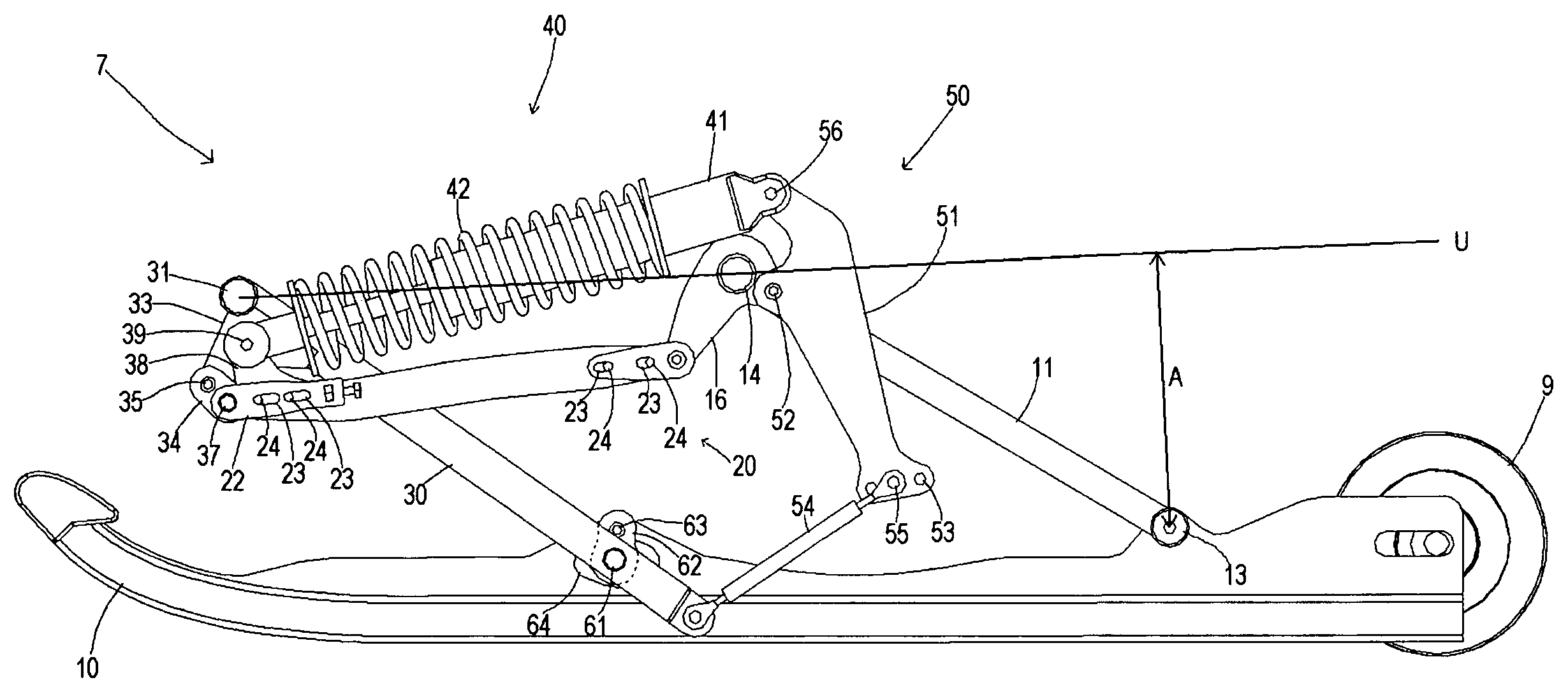
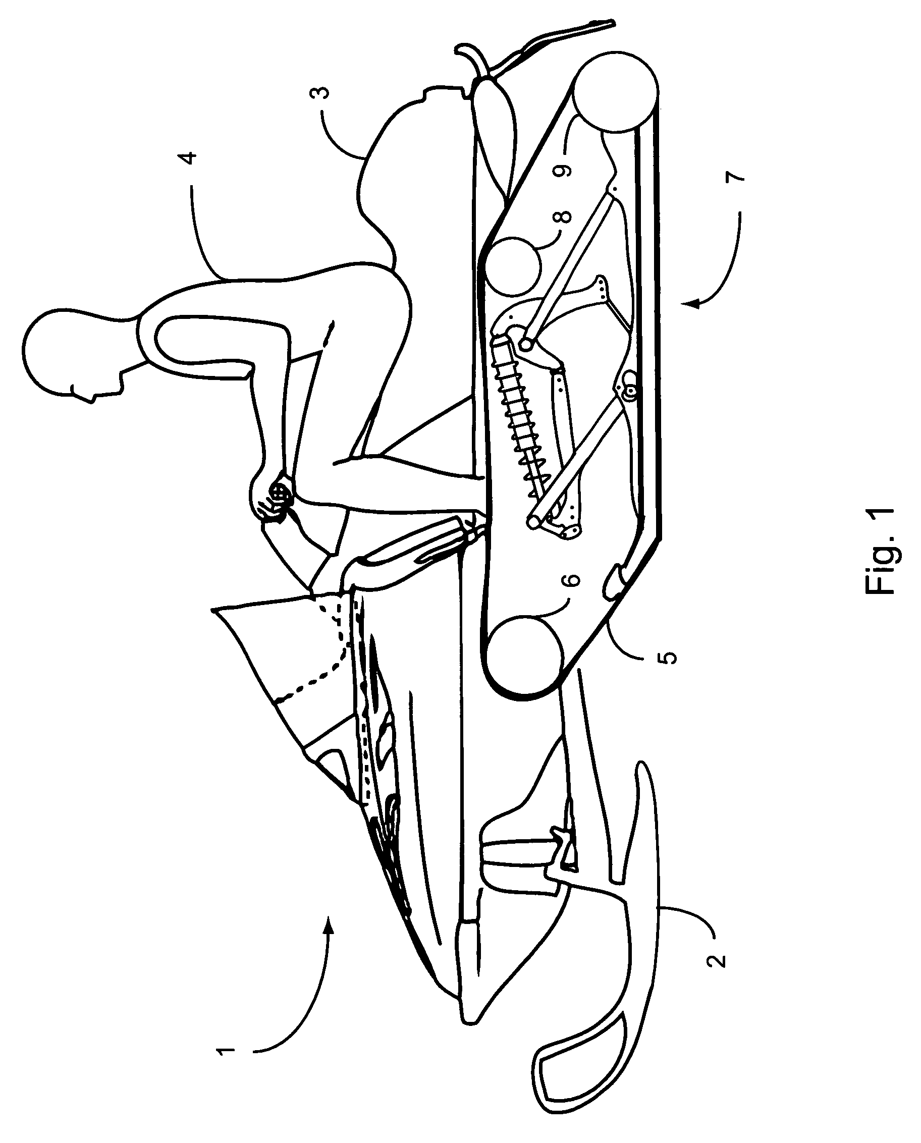
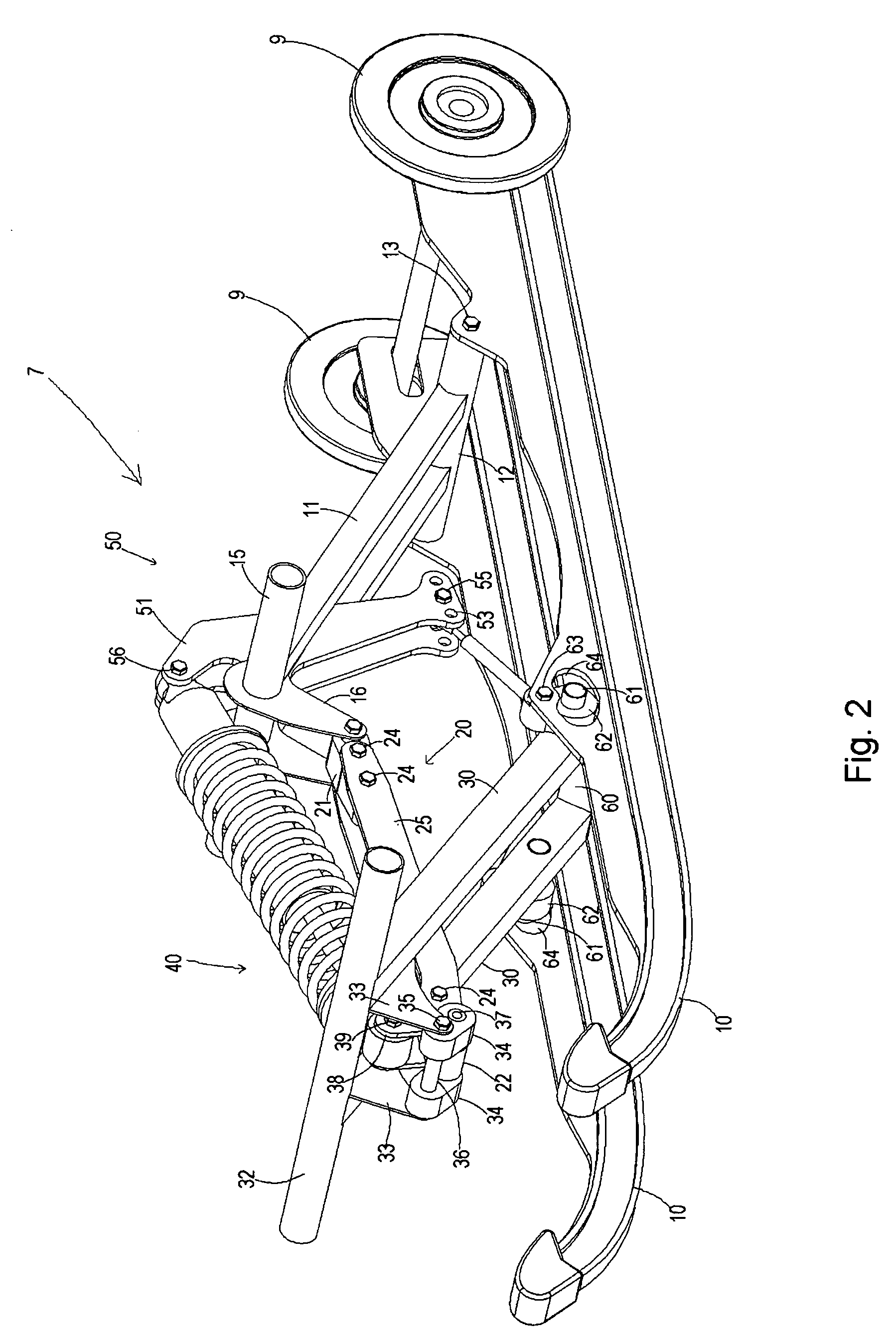
[0039]Referring to FIG. 1, a snowmobile 1 is shown generally with a pair of front skis 2, a seat 3 for supporting a rider 4 and a rear track 5. The rear track 5 is driven by a front drive pulley 6 and supported by a track suspension 7 according to the present invention. The track suspension 7 is mounted to the underside of the snowmobile 1 beneath the seat 3 within a tunnel that partially encloses the track 5, drive pulley 6 and suspension 7. A pair of running boards (which have been omitted to better show the invention) for supporting the rider's feet are provided on either side of the tunnel. The drive pulley 6 shown in FIG. 1 rotates in a counterclockwise direction. During throttle-induced acceleration of the snowmobile 1, the tension of the track 5 increases between the drive pulley 6, upper idler 8 and lower idler 9. The increased track tension causes the suspension to compress, particularly at the rear, and the lower idler 9 to move toward the underside of the snowmobile. This...


PUM


Abstract

A rear track suspension for a snowmobile having a single resilient element for biasing both the front and rear arms. The slide rail is permitted to pitch between first and second pitching constraints in response to terrain obstacles in a gradual manner as the motion constraints are approached. This reduces jarring of the rider when the pitching constraints are met. Suspension compression exhibits an initial falling rate motion ratio, followed by a constant rate motion ratio, followed by a rising rate motion ratio. This U-shaped motion ratio profile advantageously provides cushioning upon landing along with a resistance to bottoming out of the suspension upon full compression. The result is an improved ride without sacrificing suspension performance.

Description

CROSS-REFERENCE TO RELATED APPLICATIONS[0001]This application claims the benefit of U.S. patent application 60 / 642,508, filed Jan. 11, 2005, which is incorporated herein by reference.FIELD OF THE INVENTION[0002]The invention relates to rear track suspensions for snowmobiles. More particularly, the invention relates to a rear track suspension wherein the front and rear suspension arms interact to varying degrees as the suspension travels through its full range of motion. Even more particularly, the invention relates to rear track suspension wherein movement of both the front and rear suspension arms is dampened using a single resilient element.BACKGROUND OF THE INVENTION[0003]Modem snowmobiles typically have two skis for supporting the front of the machine and to provide steering and a rubber track for supporting the rear of the machine and to provide traction force. The rider is typically positioned anywhere from directly over the center of the track to over the front of the track, ...

Claims


Application Information

Patent Timeline
Patent Type & Authority Patents(United States)
IPC IPC(8): B62M29/00
CPCB62M27/00B62M27/02B62M2027/026
Inventor VISSCHER, PETER
Owner WESTERN ONTARIO THE UNIV OF
Learn More