Golf club head and manufacturing method therefor

a golf club and manufacturing method technology, applied in the field of golf club heads, can solve the problems of insufficient engagement strength, prone to cracking, and brazing area in the front edge of the cover plate, and achieve the effect of improving the reliability of engagemen

Inactive Publication Date: 2008-07-08
FUSHENG PRECISION
View PDF11 Cites 26 Cited by
  • Summary
  • Abstract
  • Description
  • Claims
  • Application Information

AI Technical Summary

Benefits of technology

[0007]An object of the present invention is to provide a golf club head that provides improved engaging reliability.
[0008]Another object of the present invention is to provide a golf club head that has a simplified structure.
[0009]A further object of the present invention is to provide a method for manufacturing a golf club head with improved engaging reliability.
[0011]In accordance with an aspect of the present invention, a golf club head includes a body having at least one assembling opening and at least one cover plate mounted in the at least one assembling opening. A plurality of spaced spot welding points are provided along a joint area between the at least one cover plate and the perimeter wall delimiting the at least one assembling opening. A brazing bonding portion is located between a pair of the spaced spot welding points adjacent to each other. The spot welding points and the brazing bonding portions securely fix the at least one cover plate in the at least one assembling opening to improve the bonding reliability.

Problems solved by technology

On the other hand, if the cover plate is mounted to the top opening by brazing to avoid generation of the recessions, sufficient engaging strength could not be obtained between a front edge of the cover plate and a perimeter wall delimiting the top opening.
As a result, the brazing area in the front edge of the cover plate (that is adjacent to the striking face and thus has a relatively larger deformation when subjected to momentum during striking) is liable to crack due to the momentum.
Further, the cover plate could not be manufactured by casting or forging that is suitable for rapid manufacture purposes.
In other words, complex manufacturing processes are required and the cost is increased.

Method used


Image

  • Golf club head and manufacturing method therefor
  • Golf club head and manufacturing method therefor
  • Golf club head and manufacturing method therefor

Examples


first embodiment

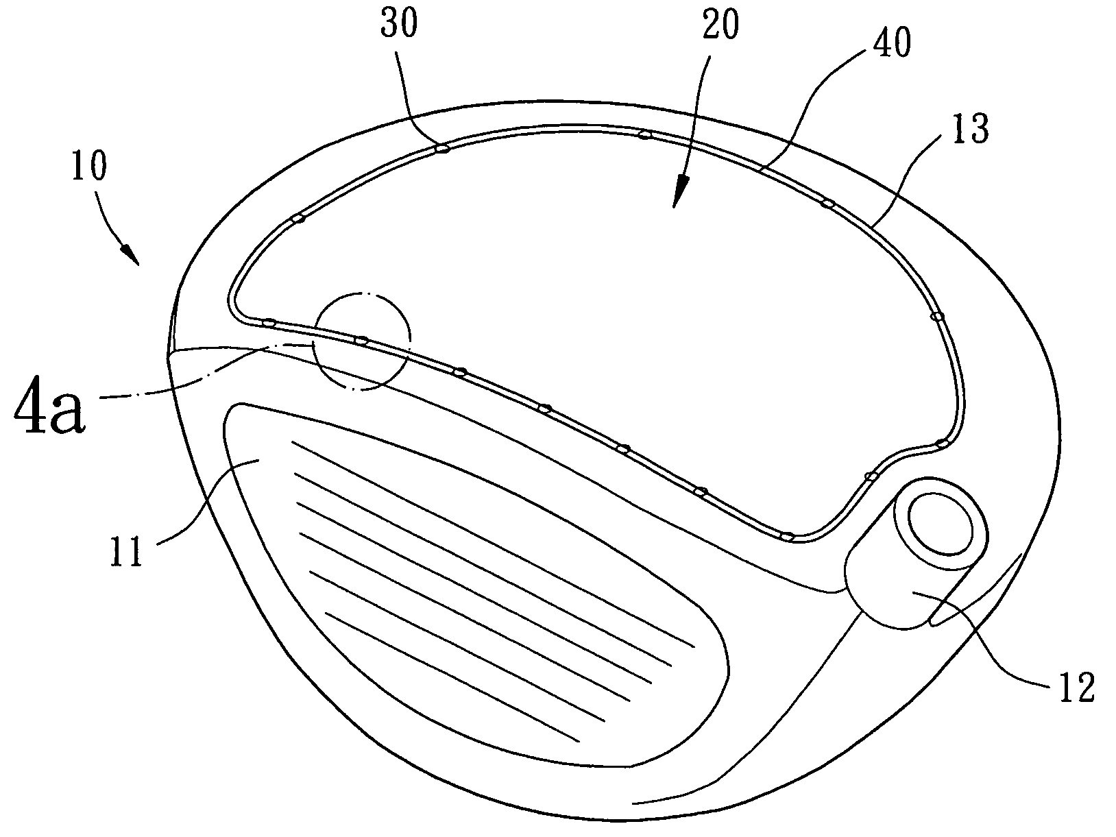
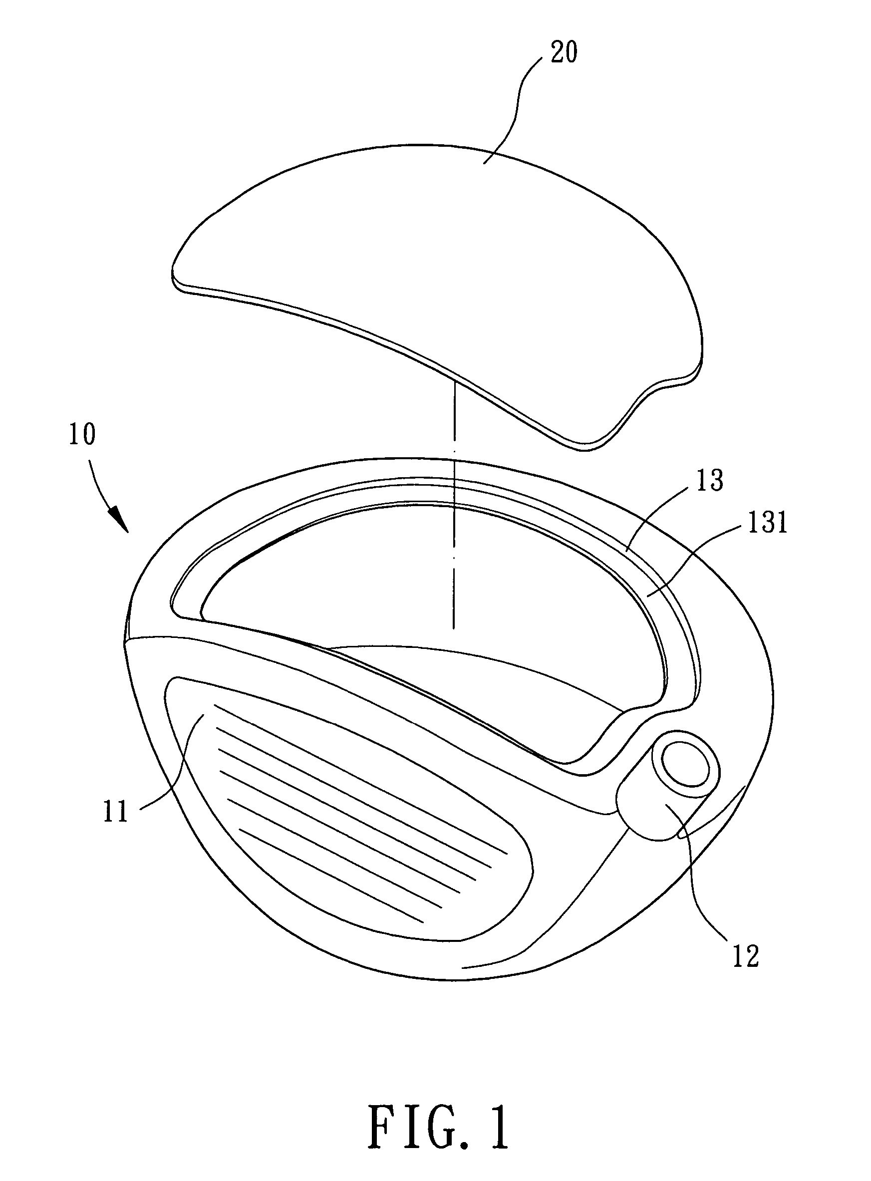
[0040]Referring to FIG. 1, a golf club head in accordance with the present invention comprises a body 10 and a cover plate 20 that are bonded together by high-energy spot welding and high-temperature brazing. In the illustrated embodiment, the golf club head is of wood type. Nevertheless, the structure of the golf club head in accordance with the present invention can be used as golf club heads of other types, such as iron type, utility type, putter type, etc.

[0041]Still referring to FIG. 1, the body 10 includes a striking plate 11, a hosel 12, and at least one assembling opening 13. In this embodiment, the striking plate 11 is integrally formed with the body 10 or fixed to a front side of the body 10 by welding, brazing, bonding, insertion, or screwing. Thus, a striking face is provided on the front side of the body 10 for striking a golfball (not shown). Similarly, the hosel 12 is integrally formed with the body 10 or fixed to a side of the body 10 by welding, brazing, bonding, in...

second embodiment

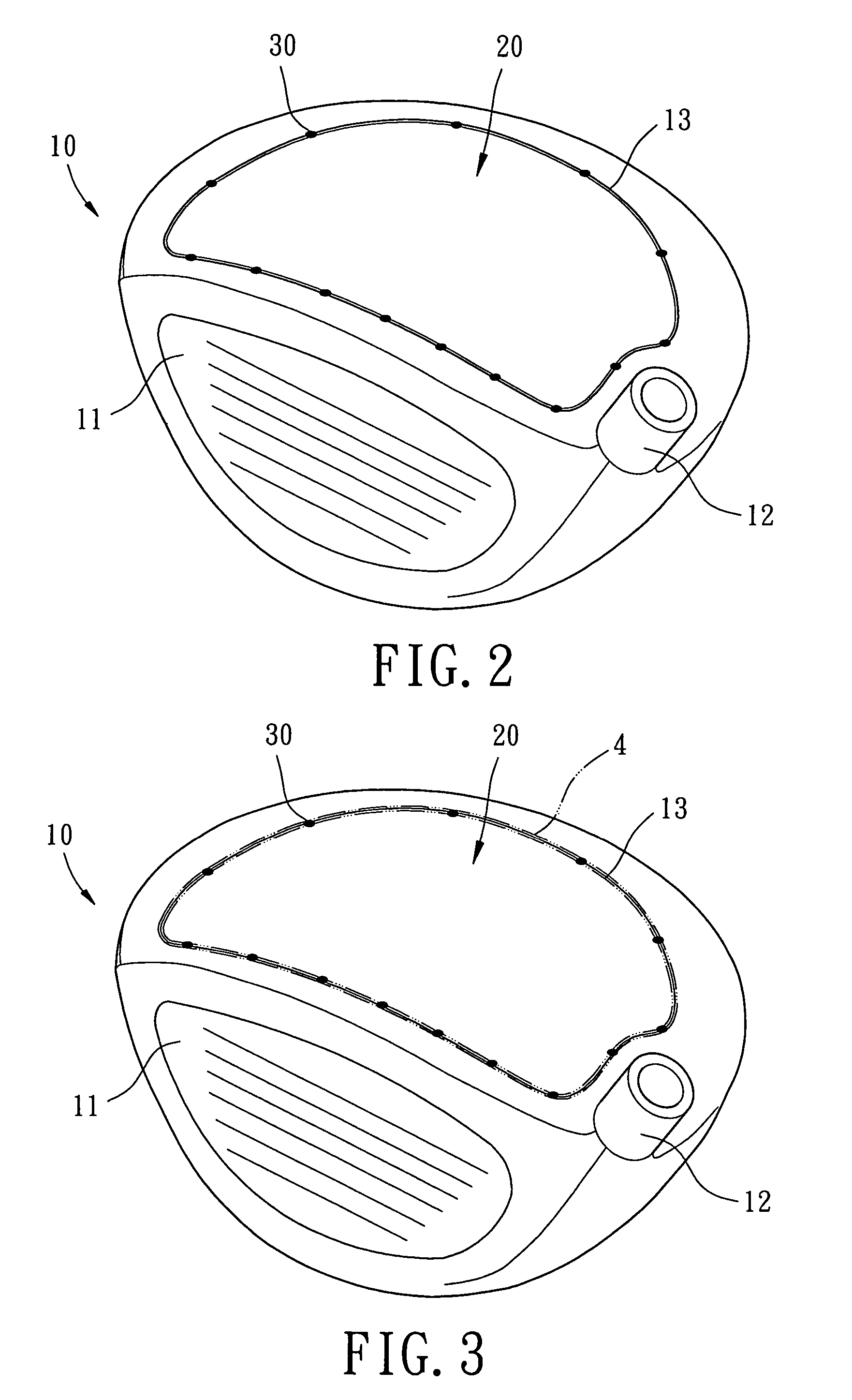
[0048]FIGS. 5 and 5a illustrate the golf club head in accordance with the present invention, wherein the perimeter wall delimiting the assembling opening 13 includes a perimeter flange 14 projecting outward. The perimeter flange 14 prevents the brazing material 4 from flowing outward during the high-temperature brazing procedure. This assures filling of a sufficient amount of molten brazing material 4 into the gaps between the cover plate 20 and the perimeter wall delimiting the assembling opening 13. In other words, the perimeter flange 14 assures reliable bonding of the brazing bonding portions 40. The perimeter flange 14 is removed by grinding after brazing.

[0049]FIGS. 6 and 6a illustrate a third embodiment of the golf club head in accordance with the present invention. In this embodiment, the cover plate 20 includes a perimeter flange 21 along a bottom of a perimeter thereof, and the stepped portion 131 in the assembling opening 13 in the first embodiment is omitted. Thus, the c...


PUM


Abstract

A golf club head includes a body having at least one assembling opening and at least one cover plate mounted in the at least one assembling opening. A plurality of spaced spot welding points are provided along a joint area between the cover plate and the perimeter wall of the assembling opening. A brazing bonding portion is located between a pair of the spaced spot welding points adjacent to each other. The spot welding points and the brazing bonding portions securely fix the cover plate in the assembling opening to improve the bonding reliability.

Description

BACKGROUND OF THE INVENTION[0001]1. Field of the Invention[0002]The present invention relates to a golf club head and a method for manufacturing the golf club head.[0003]2. Description of Related Art[0004]It is a trend to reduce the thickness of a member (e.g., a cover plate) of a golf club head for improving elastic deformability of the member. It is therefore an important task to reduce the thickness of the member while securely mounting the member on the golf club head.[0005]The member is generally mounted to the golf club head by welding or brazing. For example, a cover plate can be fixed in a top opening of a golf club head by welding or brazing. In a case that the thickness of the cover plate is reduced to a certain extent and that the cover plate is mounted to the top opening by conventional welding such as Argon welding, recessions are apt to be formed in the seam along a perimeter of the cover plate. The qualified product rate is thus low. On the other hand, if the cover pl...

Claims


Application Information

Patent Timeline
Patent Type & Authority Patents(United States)
IPC IPC(8): A63B53/04A63B53/02A63B102/32
CPCA63B53/0466A63B2053/0416A63B2053/0437A63B53/0487A63B53/047A63B53/0437A63B53/0416
Inventor LO, LAI-FA
Owner FUSHENG PRECISION
Why Eureka
Try Eureka