System and method for detecting and de-interleaving radar emitters

a radar and emitter technology, applied in the field of radar identification, can solve the problems of aircraft not knowing whether, and the aircraft is not able to determin

Active Publication Date: 2008-07-08
HARRIS CORP
View PDF9 Cites 78 Cited by
  • Summary
  • Abstract
  • Description
  • Claims
  • Application Information

AI Technical Summary

Problems solved by technology

Unless these signals are sorted and separated from each other, it is not possible for the aircraft to determine the types of classes of radars it is about to encounter.
It does not know whether the radars are hostile and does not know whether the radars present a high or low threat to the incoming aircraft.

Method used


Image

  • System and method for detecting and de-interleaving radar emitters
  • System and method for detecting and de-interleaving radar emitters
  • System and method for detecting and de-interleaving radar emitters

Examples


Embodiment Construction

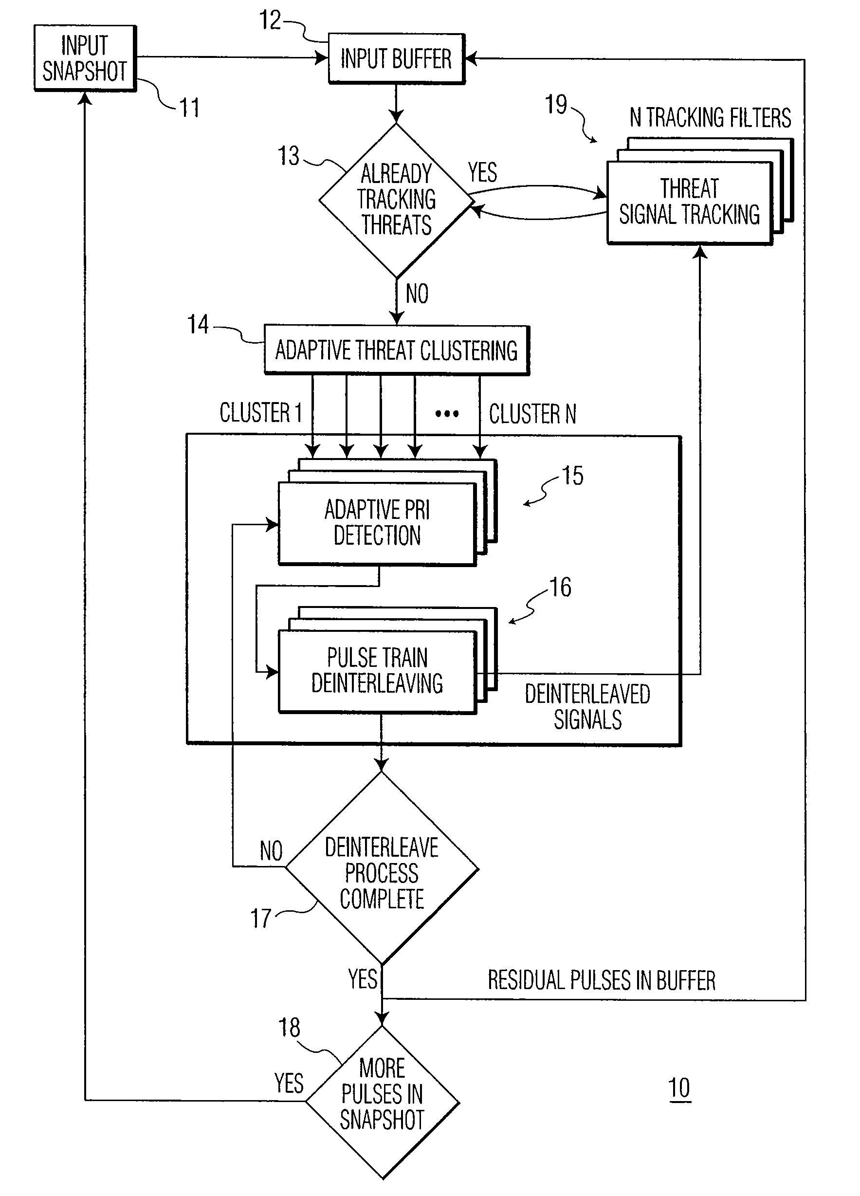
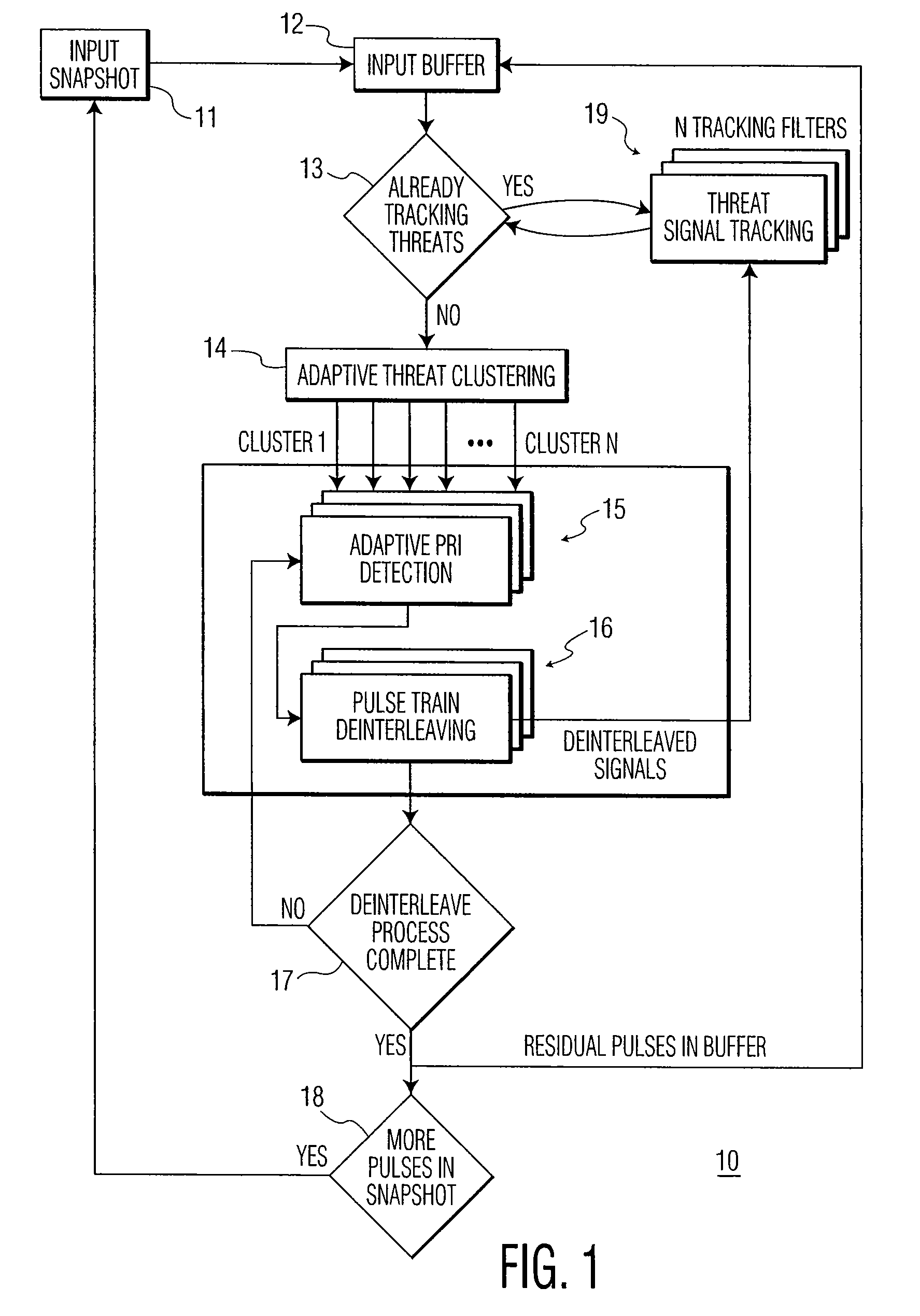
[0027]The proliferation of radar threats agile in frequency (PRF) and / or pulse repetition interval (PRI) has placed an ever-increased burden on radar warning receiver (RWR) and electronic counter measures (ECM) systems to correctly intercept, identify and countermeasure these threats. As will be explained, the present invention performs threat clustering and pulse train de-interleaving of threat radars in various dense electronic warfare (EW) environments.

[0028]Referring to FIG. 1, there is shown a functional block diagram of a system for radar threat detection and pulse train de-interleaving, in accordance with an embodiment of the present invention. The radar detection and pulse train de-interleaving system, generally designated by 10, includes input snapshot module 11, input buffer module 12, adaptive threat clustering module 14, adaptive PRI detection module 15, pulse train de-interleaving module 16 and threat signal tracking module 19. These modules are described below.

[0029]In...


PUM


Abstract

A method of classifying radar emitters includes the steps of: (a) receiving pulses from multiple radar emitters; (b) categorizing received pulses based on pulse data descriptors (PDWs); (c) forming clusters of received pulses based on the PDWs; and (d) de-interleaving pulses from the cluster using one of a differential time of arrival (DTOA) histogram technique, a spectrum estimation technique, or a Hough transform technique. Step (a) includes receiving the pulses during a predetermined time interval and storing the received pulses as a snapshot representing the pulses present during the predetermined time interval.

Description

TECHNICAL FIELD[0001]The present invention relates, in general, to radar identification. More specifically, the present invention relates to sorting signals received from multiple emitters into data clusters, and processing each data cluster to obtain de-interleaving of pulse trains from the multiple emitters.BACKGROUND OF THE INVENTION[0002]Radars emit a variety of signals that may characterize and identify them. Each radar may emit a specific pulse amplitude and a specific fixed radio frequency (RF) or a variable RF ranging over a fixed bandwidth. Each may emit a fixed pulse repetition frequency (PRF) or a fixed pulse repetition interval (PRI) and may be of a certain pulse width (PW).[0003]A radar may also emit a fixed, dwell-switched PRI or a multiple-step, multiple-position staggered PRI. In addition, a radar may emit a pattern-type of PRI, such as a sawtooth, triangular, sinusoidal, jittered, or pseudo-random pattern.[0004]An aircraft flying into a region with an onboard wideba...

Claims


Application Information

Patent Timeline
Patent Type & Authority Patents(United States)
IPC IPC(8): G01S7/36
CPCG01S7/021
Inventor WANG, PAUL C.ORR, MATTHEWSPARROW, MITCHELLAPA, MARTIN
Owner HARRIS CORP
Why Eureka
Try Eureka