Image display method and image display system

a technology of image display and image, applied in the field of image display system and image display method, can solve the problem of not being able to provide the evaluation of an object in a real space with a sense of actual siz

Active Publication Date: 2008-07-08
CANON KK
View PDF9 Cites 25 Cited by
  • Summary
  • Abstract
  • Description
  • Claims
  • Application Information

AI Technical Summary

Problems solved by technology

However, the method in which 3D-CAD data is displayed as 3D-CG on a screen of a computer can provide evaluation in a virtual space but cannot provide evaluation of an object in a real space with a sense of actual size.
The method in which a simple prototype (simple mock-up) is created by using a rapid prototyping apparatus is effective for recognizing a rough form but does not reconstruct detail information, such as design and / or form details and colors, designed under 3D-CAD, due to limitations in processing accuracy, material and so on.

Method used


Image

  • Image display method and image display system
  • Image display method and image display system
  • Image display method and image display system

Examples


first embodiment

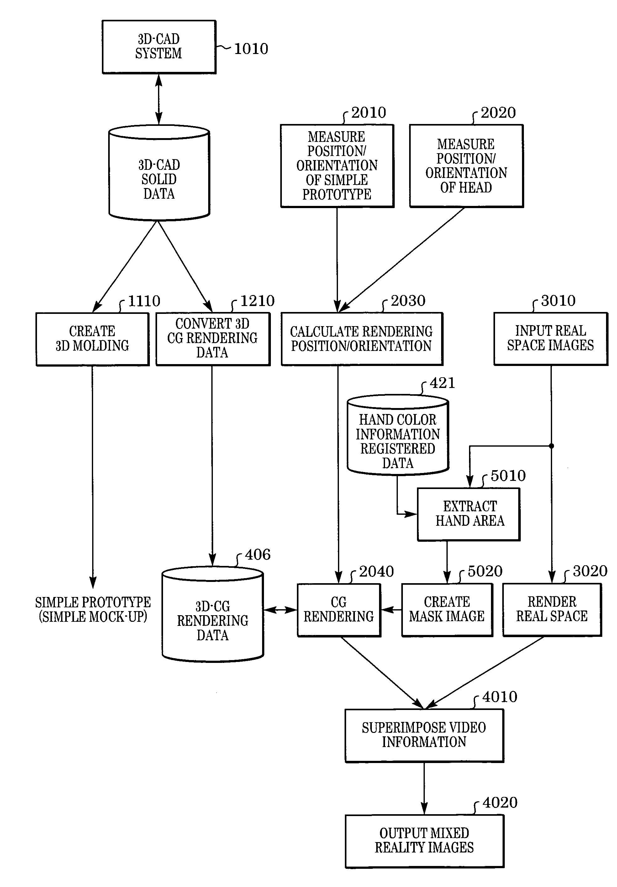
[0036]A mixed reality system according to a first embodiment will be described below. The mixed reality system arranges a simple prototype (simple mock-up) created based on three-dimensional data created by 3D-CAD and color of the background for easy extraction of a part corresponding to the hand of an operator on 3D-CG data displayed over the simple prototype.

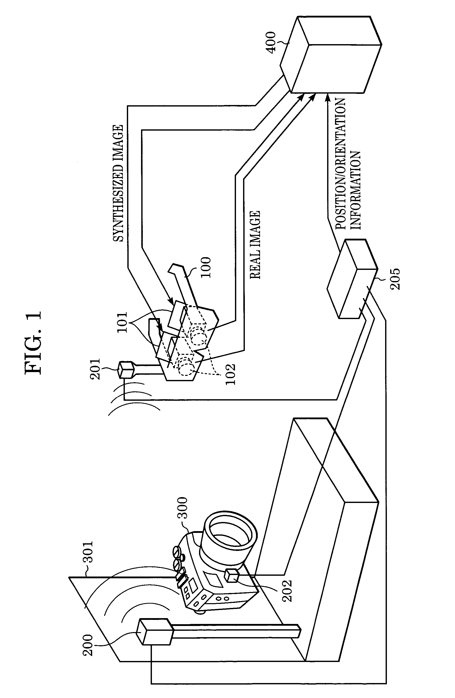
[0037]FIG. 1 shows a system construction according to the first embodiment.

[0038]FIG. 1 includes a head-mounted image input / output apparatus (head mounted-display abbreviated to HMD) 100 to be mounted at the head of an observer for observing an image resulting from synthesis of real space and virtual space images. FIG. 1 further includes a magnetic transmitter 200, magnetic sensors 201 and 202, a position / orientation measuring apparatus 205, a simple prototype (simple mock-up) 300, and a base 301. The magnetic transmitter 200 generates a magnetic field. The magnetic sensors 201 and 202 are used for measuring changes in a magne...

second embodiment

[0064]According to the first embodiment, the position / orientation measurement is performed magnetically, for example. However, in the magnetic position / orientation measurement, some environments may cause instability in precision for measurement. When a metal object exists near a magnetic transmitter, for example, the magnetic field may become turbulent, which may cause a magnetic sensor to output unstable values. Furthermore, as the distance between the magnetic transmitter and the magnetic sensor increases, the measurement precision may decrease, which is a problem. The problem in measurement precision is caused not only in a magnetic sensor but also in various type of measuring apparatus.

[0065]Accordingly, a mixed reality system according to the second embodiment corrects a position and an orientation based on real space image data in an information processor 400 so as to improve the measurement precision. For example, as shown in FIG. 6, a marker for image recognition is attache...

third embodiment

[0091]According to a third embodiment, giving a marker to a simple prototype (simple mock-up) according to a second embodiment is achieved by giving mark form data to 3D-CAD data of a simple prototype. A processing flow according to the third embodiment will be described with reference to FIG. 11. The same reference numerals are given to the same steps as those of the processing (FIG. 10) according to the second embodiment. A construction of a mixed reality system according to the third embodiment is the same as the construction (FIG. 9) of the second embodiment.

[0092]First of all, a three-dimensional CAD system 1010 is used to give a mark form data to 3D-CAD solid data (step 1011) and record position information thereon (step 1012). In other words, a mark is given to 3D-CAD solid data as form data in the 3D-CAD solid data. Here, mark form data can include multiple intersecting channels or multiple small holes or projections indicating the intersections (see FIGS. 7A and 7B). In thi...


PUM


Abstract

Real space image including a simple prototype created based on three-dimensional CAD data is captured by an image input apparatus. A position / orientation measuring apparatus measures positions and orientations of the image input apparatus and simple prototype. An information processor captures position / orientation information representing the position and orientation of the simple prototype in the image captured by the image input apparatus 102. The information processor further extracts a hand area from an image, renders a three-dimensional computer graphic image on the simple prototype, excluding the extracted hand area, in the image based on the position / orientation information and the three-dimensional CAD data, and synthesizes the image and the three-dimensional computer graphic image. Here, the simple prototype has a different color from a color of the hand area.

Description

[0001]This application claims priority from Japanese Patent Application No. 2003-341627 filed on Sep. 30, 2003, which is hereby incorporated by reference herein.BACKGROUND OF THE INVENTION[0002]1. Field of the Invention[0003]The present invention relates to an image display system and image display method for providing an observer with virtual space image information over real space image information at a given viewpoint.[0004]2. Description of the Related Art[0005]Hitherto, a mixed reality system provides a user with a synthesized image by merging a real space image and a virtual space image created in accordance with a user's viewpoint and a user's viewing direction. A mixed reality system disclosed in Japanese Patent Laid-Open No. 11-136706 can provide an observer with a feeling that a virtual object actually exists in a real space such that the user can perform more real observation with a sense of actual size than a conventional virtual reality system (VR system).[0006]On the o...

Claims


Application Information

Patent Timeline
Patent Type & Authority Patents(United States)
IPC IPC(8): G09G5/00G06T7/00G06T19/00G06T7/60G06T17/00H04N15/00
CPCG06T7/0024G06T19/006G06T17/00G06T15/10G06T19/20G06T2219/2012G06T7/30
Inventor ENDO, TAKAAKIFUJIKI, MASAKAZUKUROKI, TSUYOSHI
Owner CANON KK
Why Eureka
Try Eureka