System and method for aerial image sensing

a technology of aerial image and sensing method, which is applied in the field of sensing an aerial image, can solve the problems of limited resolution of the sensed image, limited imaging performance, and lithography masks in high-energy ranges of the electromagnetic spectrum, and achieve the effect of enhancing the photo-reception efficiency of the photo-sensitive area of each photo-detector under the apertur

Active Publication Date: 2005-06-14
THE BOARD OF TRUSTEES OF THE LELAND STANFORD JUNIOR UNIV +1
View PDF67 Cites 69 Cited by
  • Summary
  • Abstract
  • Description
  • Claims
  • Application Information

AI Technical Summary

Benefits of technology

[0015]In one embodiment, the photo-electron emission device may include an electron-multiplying cathode to amplify the emitted electrons and to isolate the vacuum surrounding the negative electron affinity photocathode from that elsewhere in the system. Indeed, it may be advantageous to employ an electron-multiplying cathode having a dimension such that the emitted electrons impacting on the electron-multiplying cathode cause emission of substantially thermalized electrons. In this way, the thermalized electrons may have a tight energy spread that, in certain instances, may be advantageous for measurement issues.
[0020]In one embodiment, the re-charging electron source is provided by an array of scanning micro-tips. The tips may be similar to those used in a conventional atomic force microscope (AFM). This approach provides much higher throughput due to the parallel operation of the array of tips. In addition, this approach may allow very compact sensor to be built due to the short distance between the tips and the photo-conducting layer.
[0022]In another embodiment of this aspect of the invention, a photo-detector enhancement material (for example, a photo-sensitive semiconductor material) may be grown or deposited within the aperture. In this way, the photo-reception efficiency of the photo-sensitive area of each photo-detector under the aperture may be enhanced.

Problems solved by technology

The same optics also limits the imaging performance by introducing diffraction, aberration and other effects.
In this method, the resolution of the sensed image is limited by the sensor pixel size.
Examining masks for lithography in high-energy ranges of the electromagnetic spectrum, such as the X-ray range, presents additional challenges because of, for example, the severe limitations on imaging and lack of suitable transmission optics.

Method used


Image

  • System and method for aerial image sensing
  • System and method for aerial image sensing
  • System and method for aerial image sensing

Examples


Embodiment Construction

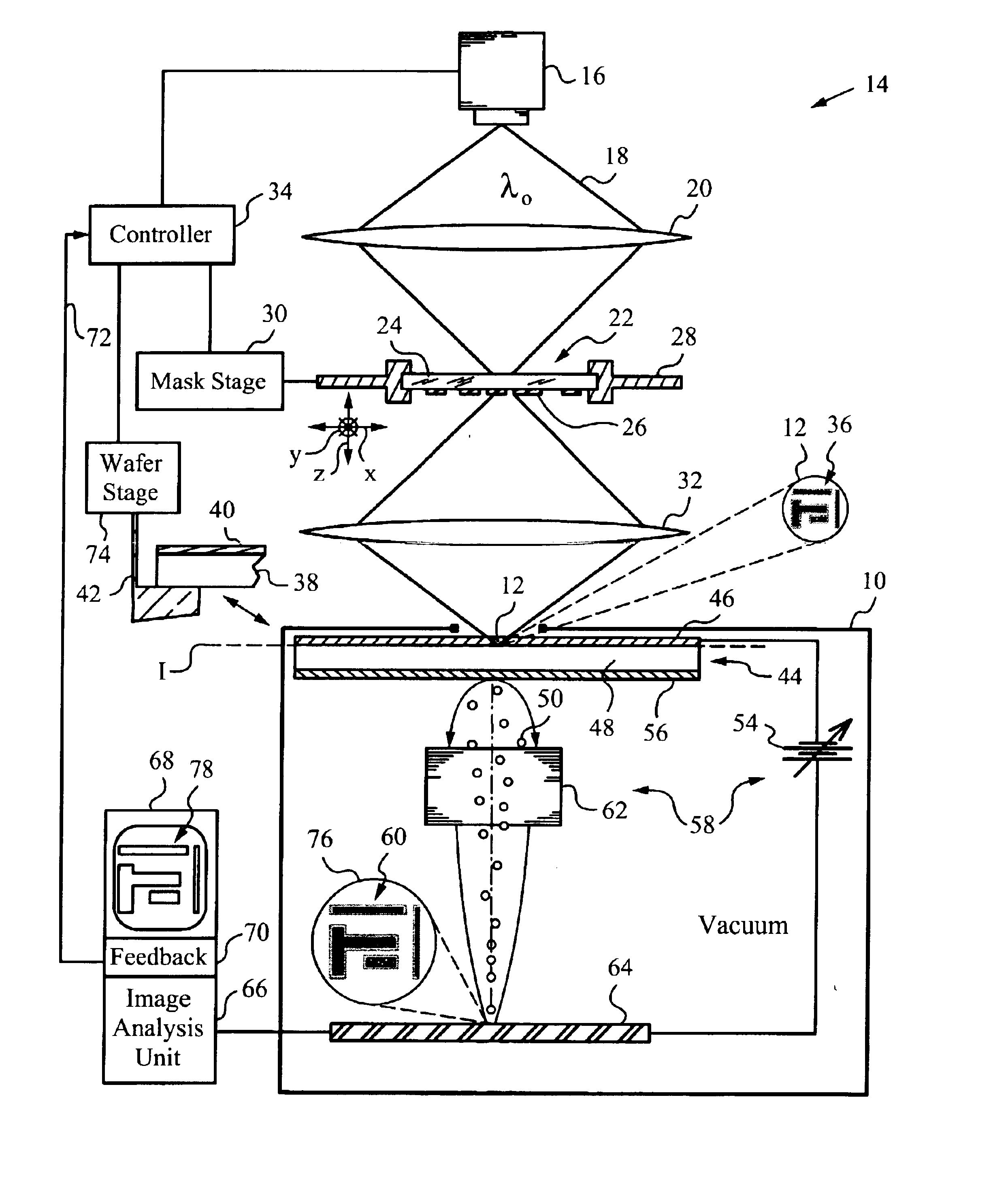
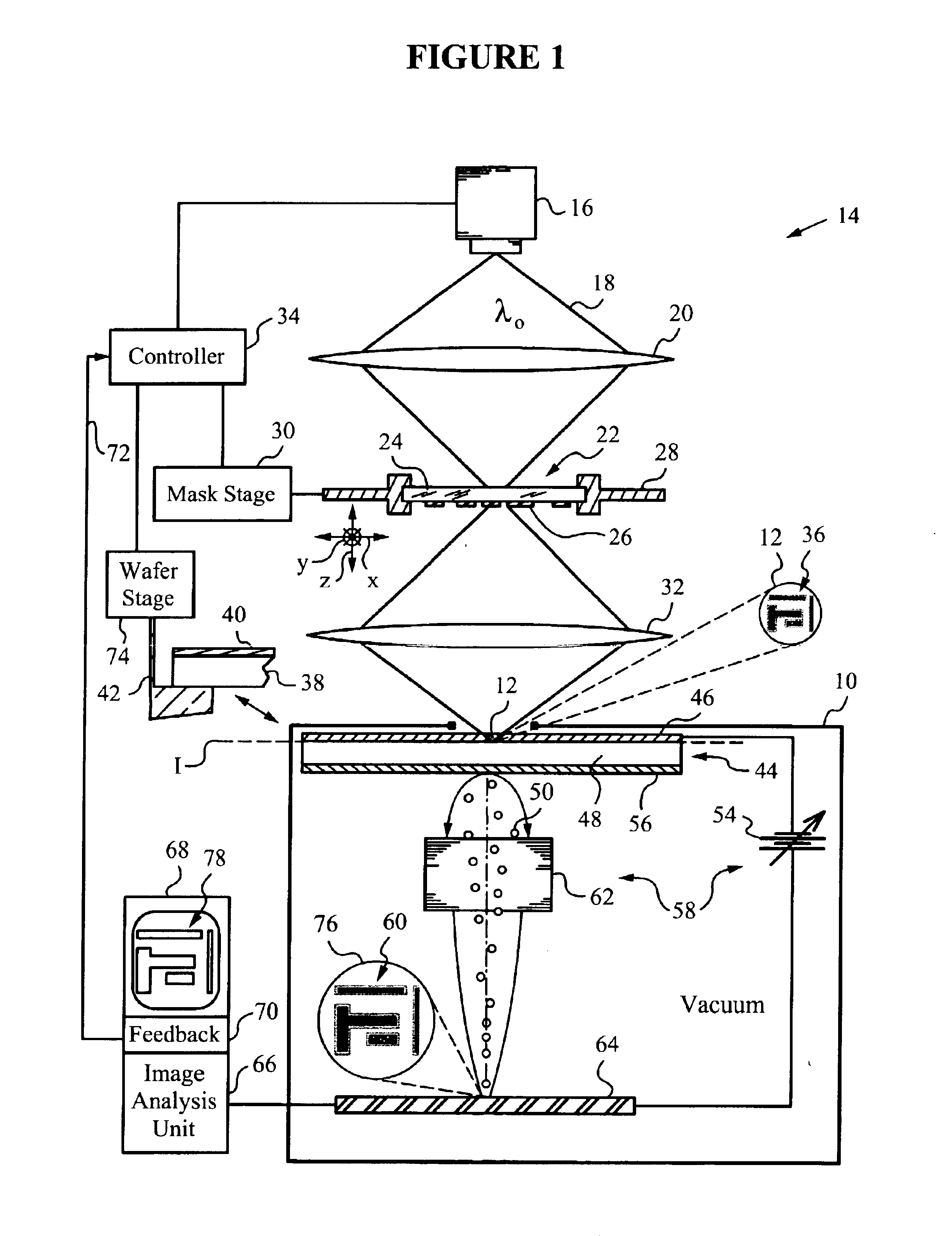
[0036]With reference to FIG. 1, apparatus 10 senses an aerial image 12 in a photolithographic device 14. Photolithographic device 14 is equipped with a light source 16 for generating light 18 at a suitable exposure wavelength λ0. Photolithographic device 14 may be integrated into or part of a photolithographic stepper or scanner. The light source 16 may be a laser (for example, a pulsed laser), a UV exposure lamp or any other source suitable for photolithography.

[0037]The photolithographic device 14 also includes condensing optics 20, in the form of a refractive lens, to collect light 18 emitted by source 16 and focus it on an object 22. It should be noted that any type of optics may be used to collect light 18 including, for example, reflective optics rather than refractive optics.

[0038]The object 22 may be a photolithographic mask made of a substrate 24 and a mask pattern 26 deposited on the surface of substrate 24. In the present embodiment, substrate 24 is transmissive to light ...


PUM

PropertyMeasurementUnit
conduction band energyaaaaaaaaaa
thickaaaaaaaaaa
thickaaaaaaaaaa

Abstract

A system to sense an aerial image produced by optical equipment used in, for example, semiconductor fabrication. In one embodiment, the system includes a photo-electron emission device which, in response to an aerial image projected thereon, emits electrons in a pattern corresponding to the light intensity distribution produced by the aerial image. Electron optics provides an enlarged pattern of the pattern in which the electrons are emitted. A sensing unit senses the enlarged pattern. In another embodiment, the system employs a photo-conducting layer to project the aerial image thereon. The photo-conducting layer, in response to the projection of the aerial image thereon, produces local charge depletion corresponding to the light intensity distribution. A steering device delivers electrons to the photo-conducting layer to produce local re-charging currents in proportion to the local charge depletion. A pattern corresponding to the aerial image may be obtained from the re-charging currents.

Description

CROSS-REFERENCE TO RELATED APPLICATIONS[0001]This application claims priority to U.S. Provisional Application Ser. No. 60 / 347,169, entitled “Aerial Image Sensing”, filed Jan. 8, 2002. The contents of this provisional patent application are incorporated by reference herein in their entirety.FIELD OF THE INVENTION[0002]The present invention relates generally to sensing an aerial image and more particularly to systems and techniques for increasing the sensing resolution of an aerial image.BACKGROUND[0003]Aerial imaging typically employs an optical imaging and projection system to project a two-dimensional aerial image onto an image plane. The location of the image plane is defined by the optics of the imaging and projection system. The same optics also limits the imaging performance by introducing diffraction, aberration and other effects. A straightforward method of sensing the aerial image is to place a conventional image sensor (for example, a conventional CCD) at the aerial image p...

Claims


Application Information

Patent Timeline
Patent Type & Authority Patents(United States)
IPC IPC(8): G03F7/20G03F1/00H01L21/027
CPCG03F7/70591G03F9/7069G03F7/70666G03F7/7085G03F7/7065G03F1/0092G03F1/84
Inventor PEASE, R. FABIAN W.YE, JUN
Owner THE BOARD OF TRUSTEES OF THE LELAND STANFORD JUNIOR UNIV
Why Eureka
Try Eureka