Staring 2-D hadamard transform spectral imager

a technology of hadamard transform and spectral imager, which is applied in the direction of spectrometry/spectrophotometry/monochromator, instruments, and optical radiation measurement, etc., can solve the problems of spectral multiplexing techniques that have the potential of increasing snr and reducing the sample rate for a given measuremen

Active Publication Date: 2006-02-07
SANDIA NAT LAB
View PDF10 Cites 71 Cited by
  • Summary
  • Abstract
  • Description
  • Claims
  • Application Information

AI Technical Summary

Benefits of technology

[0011]The present invention provides a staring 2D imaging system utilizing the TI digital micromirror device™ (DMD™) and a 2D detector. The DMD™ is programmed to apply a cyclic S-matrix Hadamard encoding scheme, in either the spatial or spectral dimension, to the entire input scene with the resulting encodegram image cube undergoing the Hadamard transform to decode the encoded dimension. Unlike the prior art for encoding the spatial dimension, one embodiment of the present invention does not require the use of a spectral discriminator (i.e. spectrograph or Fourier tran

Problems solved by technology

Such momentary changes could easily be missed by a scanning system.
Existing spectral imaging technologies do not support high-speed imagery because mechanical scanning mechanisms are too slow.
In addition, under certain noise conditions, spectral multiplexing techniques have the potential of increasing SNR and decreasing the sample rate for a given measurement.
Due to the relatively high

Method used


Image

  • Staring 2-D hadamard transform spectral imager
  • Staring 2-D hadamard transform spectral imager
  • Staring 2-D hadamard transform spectral imager

Examples


Embodiment Construction

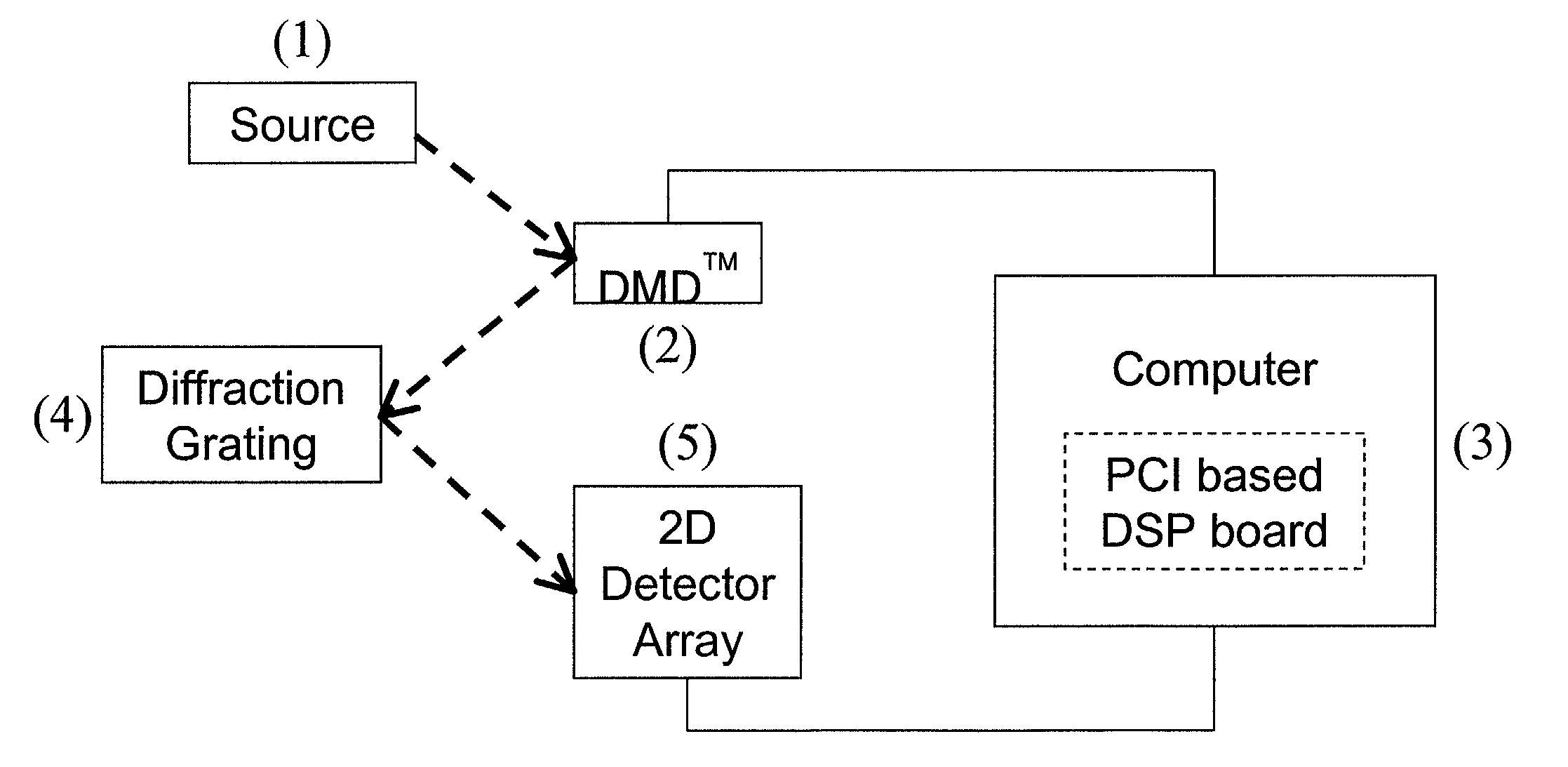
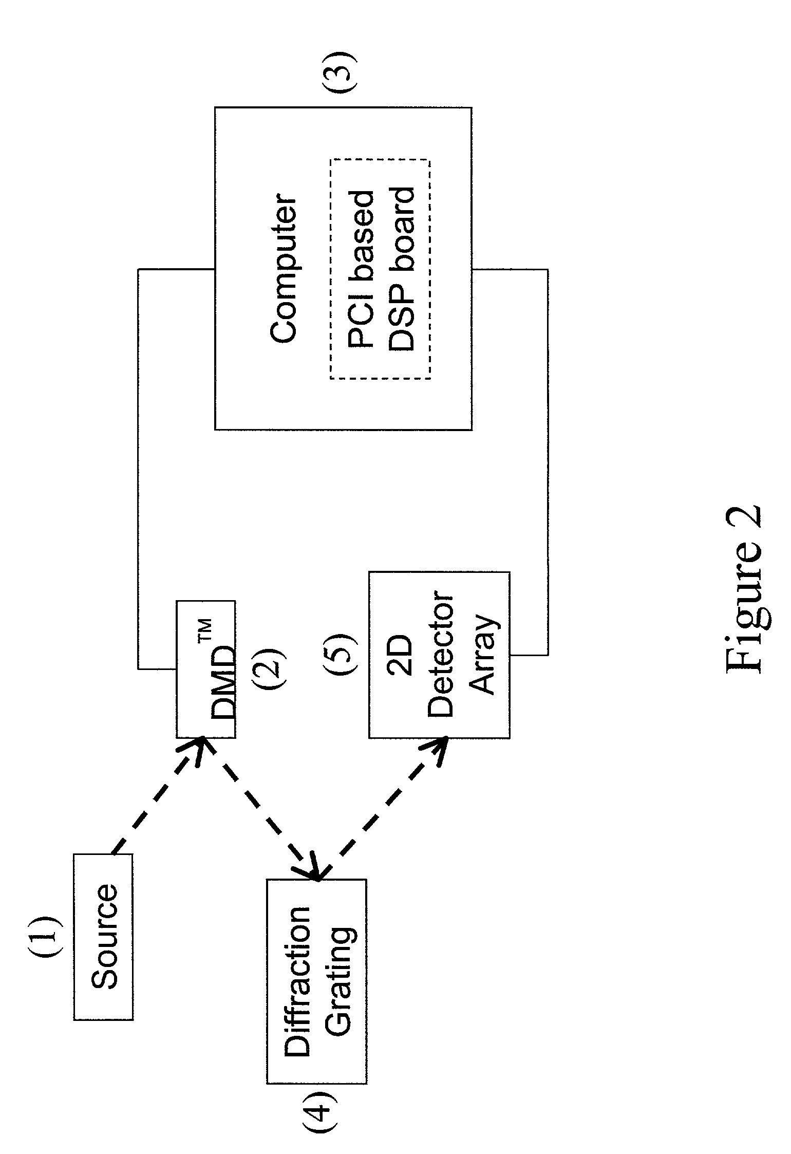
[0021]Depicted schematically in FIG. 2 are the primary components for an imaging device according to the present invention. An incoming 2D image source 1 is focused on a digital micromirror array such as DMD™2. After encoding in the spatial x-dimension on the DMD™2, the image is spectrally dispersed by a diffraction grating 4 and the spectrally dispersed, spatially Hadamard-encoded image is directed to a 2D detector array 5. The 2D detector array is read out for each element of the Hadamard encoding sequence, or once for each state of the DMD™2. This produces a sequence of data frames that carry mixed spatial and spectral information. The spatial and spectral information are separated in computer 3 by a Hadamard transform using the inversion technique with a moving window (as indicated by R(i:i+(h- 1)j), outlined in FIG. 5.

[0022]A second embodiment of the present invention is shown in FIG. 3. The dispersed 2D image source 1 is focused on to a DMD™3 by a split-Offner relay. A diffrac...


PUM


Abstract

A staring imaging system inputs a 2D spatial image containing multi-frequency spectral information. This image is encoded in one dimension of the image with a cyclic Hadamarid S-matrix. The resulting image is detecting with a spatial 2D detector; and a computer applies a Hadamard transform to recover the encoded image.

Description

[0001]The United States Government has rights in this invention pursuant to Department of Energy Contract No. DE-AC04-94AL85000 with Sandia Corporation.CROSS REFERENCE TO RELATED APPLICATIONS[0002](Not Applicable)BACKGROUND OF THE INVENTION[0003]There is a need for staring imaging systems capable of real-time high-speed imagery in a large number of spectral bands. (A staring image is a two-dimensional image that is captured at a single point in time, such as a camera image. A scanning image is a one-dimensional image that is scanned over different points in space as a function in time to form a 2-dimensional image). A staring system would be useful for determining if momentary spectral changes occur in a two-dimensional field of view. Such momentary changes could easily be missed by a scanning system.[0004]Existing spectral imaging technologies do not support high-speed imagery because mechanical scanning mechanisms are too slow. Techniques that employ electronic scanning methods an...

Claims


Application Information

Patent Timeline
IPC IPC(8): G06K9/36G01J3/40
CPCG01J3/02G01J3/2846G01J3/2823G01J3/021
Inventor GENTRY, STEPHEN M.WEHLBURG, CHRISTINE M.WEHLBURG, JOSEPH C.SMITH, MARK W.SMITH, JODY L.
Owner SANDIA NAT LAB
Why Eureka
Try Eureka