
Battery management unit, system and method

a battery management and battery technology, applied in the field of battery management systems, can solve the problems of not performing any real control, and shortening the battery life of each battery

Inactive Publication Date: 2008-07-15
TRANSPORTATION TECH
View PDF13 Cites 102 Cited by
  • Summary
  • Abstract
  • Description
  • Claims
  • Application Information

AI Technical Summary

Benefits of technology

"The invention provides a battery management system for managing the state of charge of multiple cells or batteries connected in series. The system includes multiple battery management units, each connected to a specific battery group. Each unit includes a local charger, discharger, and sensors for measuring cell and ambient parameters. A local processor controls the charger and discharger of the group to which it is connected. The system also includes a main charger and a central processor in communication with the battery management units. The central processor receives information about the battery groups and manages the operation of the battery by selectively connecting the main charger or discharger to the appropriate battery group. The system can also include a common communication medium for communication between the local processors and the central processor. The technical effects of the invention include improved battery management and dynamic control of battery charge and discharge to maintain optimal performance."

Problems solved by technology

In these vehicles each battery can undergo regular deep cycling of its state of charge and thus each battery life expectancy is typically short.
It is undesirable to discharge a battery too far as this also shortens battery life.
A number of battery management systems are known, however they generally only perform any real control during overnight charging.
This can result in overcharging of the battery.
This does not overcome problems with state of charge cycling.
This is an expensive and complex system.
This requires an individual module with a bypass resistor arrangement for each cell and does not allow the selective charging of selected batteries.
EP0798839A2 discloses a battery management system in which an individual battery module is required for each battery making it expensive and complex.

Method used


Image

  • Battery management unit, system and method
  • Battery management unit, system and method
  • Battery management unit, system and method

Examples


Embodiment Construction

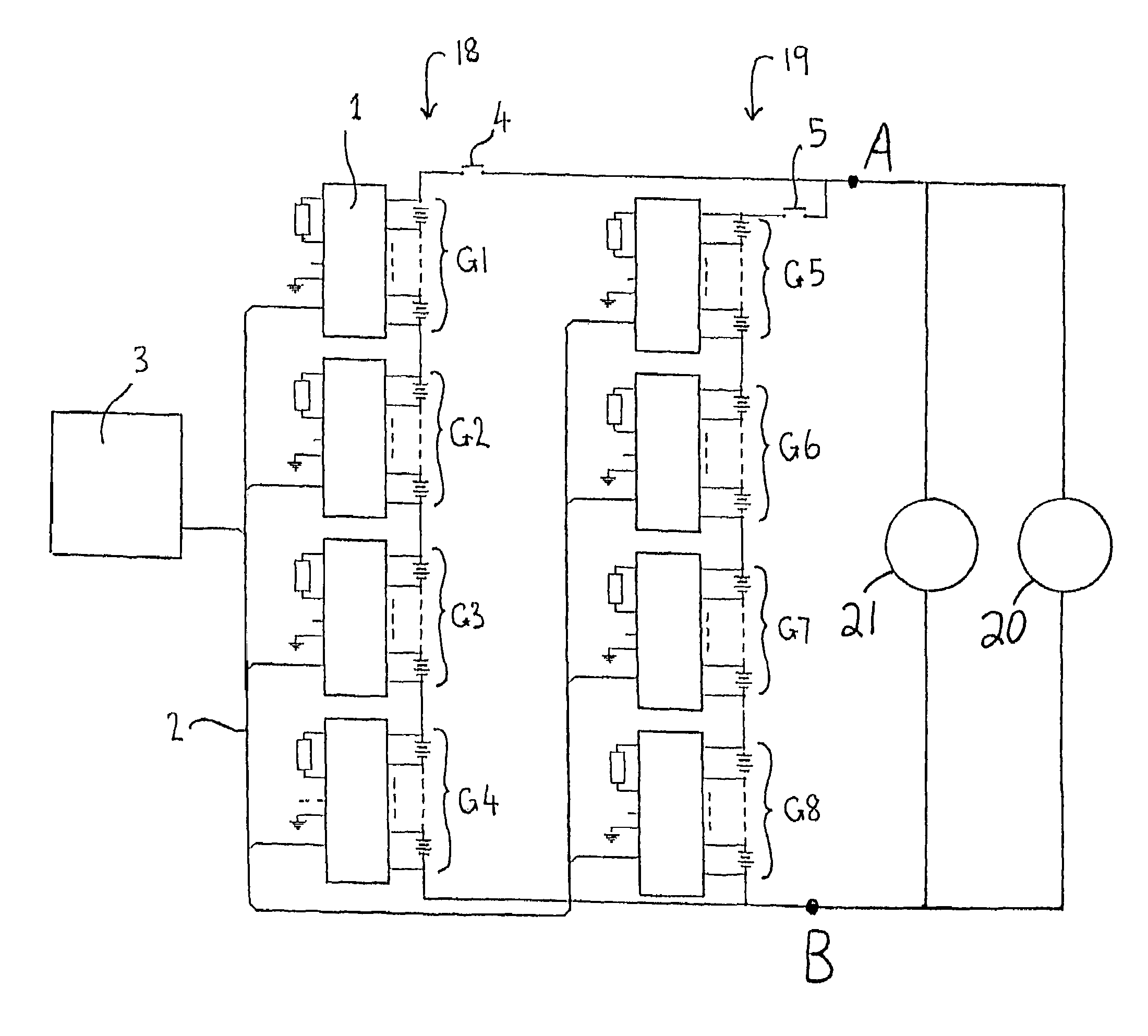
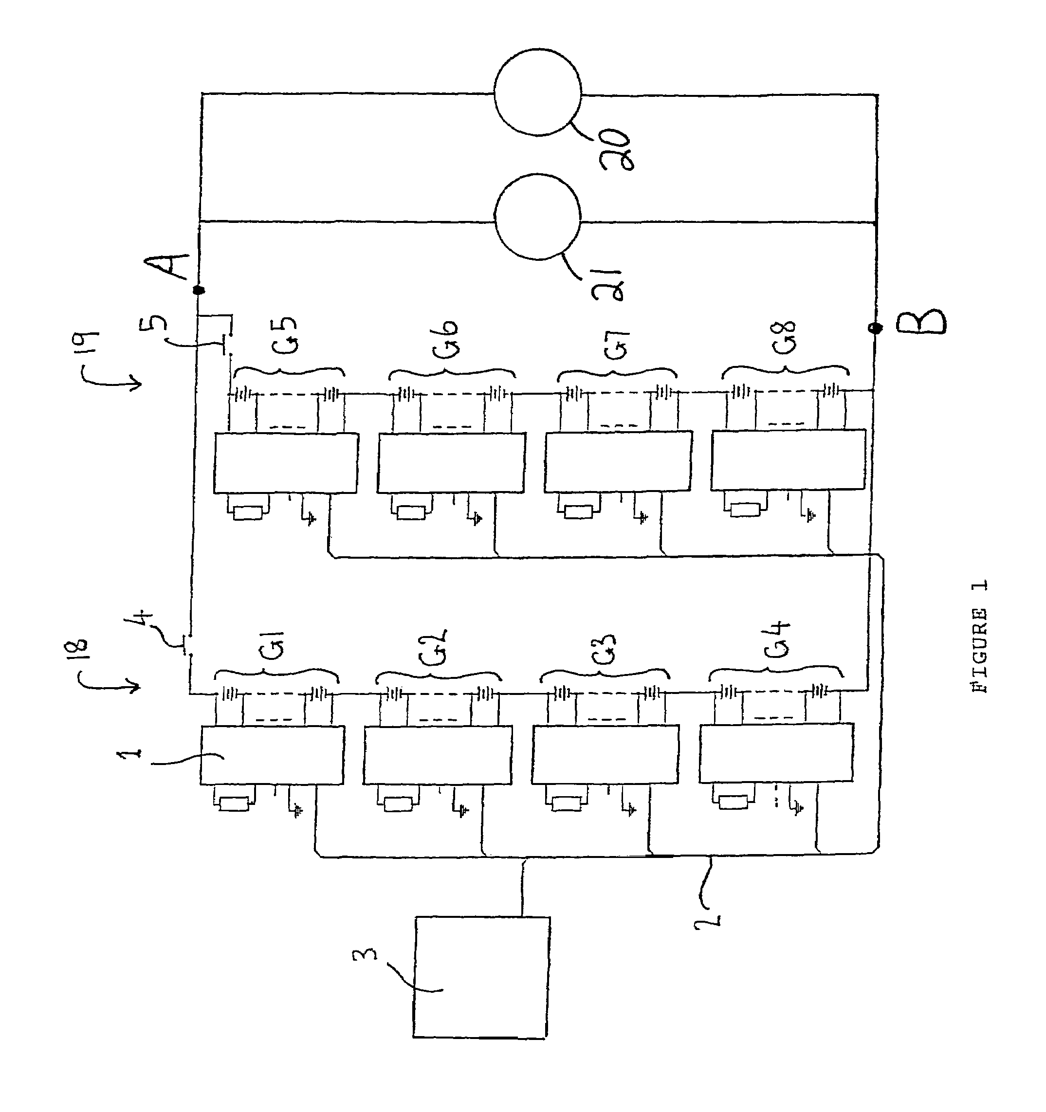
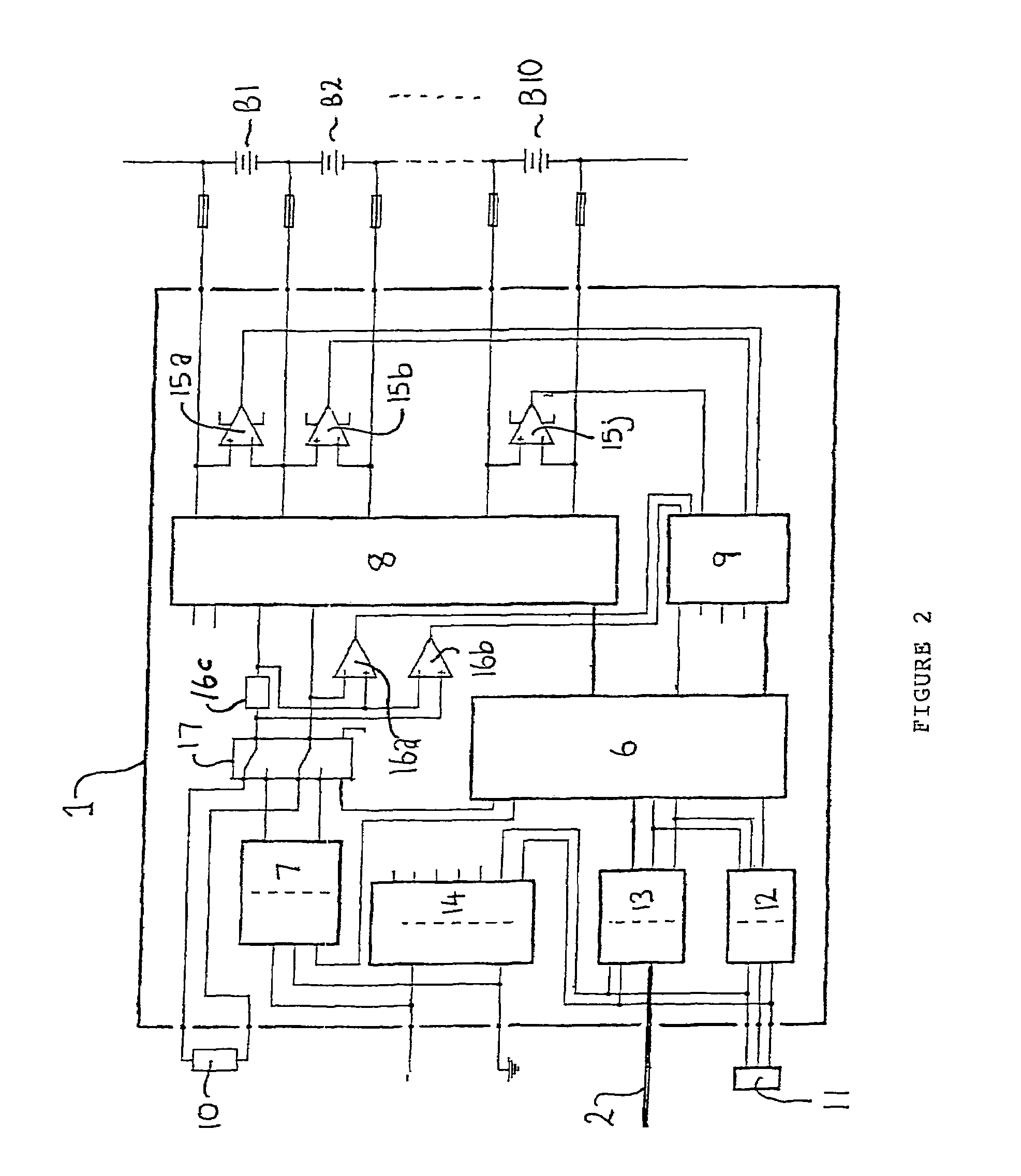
[0063]A specific example of the invention will now be described with reference to FIGS. 1 and 2, in which like numerals represent like integers. The invention will be described with reference to a particular set-up of a hybrid electric vehicle in which the battery comprises two parallel strings 18 and 19 of forty series connected 12-volt batteries. This is not critical to the invention, however, and it will become apparent to the skilled addressee that the invention is equally applicable to other battery configurations.

[0064]Referring to FIG. 1, there shown is a schematic overview of the hardware from a battery management system according to the invention. The battery comprises eighty 12-volt batteries configured in two parallel strings 18 and 19 of forty series connected 12-volt batteries. Each string 18 and 19 is further divided into four groups G1-G4 and G5-G8 comprising ten series connected 12-volt batteries. According to this battery configuration the output voltage between Bus...


PUM

PropertyMeasurementUnit
state of chargeaaaaaaaaaa
voltageaaaaaaaaaa
temperatureaaaaaaaaaa

Abstract

A battery management unit and system for managing the state of charge of cells or batteries. Each battery management unit measures cell or battery terminal voltage and provides this information to a central controller via a communication medium. Each battery management unit monitors a plurality of batteries and can selectively charge a selected battery via a charger and switch circuit or can selectively discharge a selected battery via a load and switch circuit under the control of a controller. The controller may control charging and discharging in accordance with measurements from voltage sensors or may convey information from a voltage sensors to the central controller and receive charging and discharging commands from the central controller. Charging and discharging is controlled to maintain all batteries within a desired state of charge ranged. The central controller may selectively connect a main charger or generator to a bank of batteries associated with a battery management unit.

Description

[0001]This application is the US national phase of international application PCT / NZ02 / 00046, filed Mar. 28, 2002, which designated the US. PCT / NZ02 / 00046 claims priority to New Zealand Application No. 510848, filed Mar. 30, 2001. The entire contents of these applications are incorporated herein by reference.FIELD OF THE INVENTION[0002]The invention relates to battery management systems and in particular to a system and method for managing the operation of batteries in electric vehicle applications.BACKGROUND TO THE INVENTION[0003]Electric vehicles are known in the art. They include one or more battery that supplies energy to one or more electric motors that in turn provide motive force to the vehicle. Each battery is generally charged overnight for use during the day. In these vehicles each battery can undergo regular deep cycling of its state of charge and thus each battery life expectancy is typically short. It is undesirable to discharge a battery too far as this also shortens ba...

Claims


Application Information

Patent Timeline
Patent Type & Authority Patents(United States)
IPC IPC(8): H01M10/46H02J7/02B60L11/18H01M10/44H02J7/00
CPCH02J7/0018Y02T10/7055Y02T10/70
Inventor OSBORNE, JEFFREY ROGER
Owner TRANSPORTATION TECH
Learn More