Optical sensing system and system for stabilizing machine-controllable vehicles

a sensing system and optical sensor technology, applied in the direction of remote control toys, instruments, navigation instruments, etc., can solve the problems of inability to measure or regulate the system cannot only operate correctly, and the inability to control the absolute position of the ground, etc., to achieve the effect of stabilising the flight movement, avoiding undesirable fluctuations, and accelerating the reaction of the shift sensor

Active Publication Date: 2008-07-15
IRON BIRD LLC
View PDF40 Cites 56 Cited by
  • Summary
  • Abstract
  • Description
  • Claims
  • Application Information

AI Technical Summary

Benefits of technology

[0038]Commonly used optical-mouse-sensors contain mostly 16×16 or 18×18 or a similar number of pixels in CCD-technology (charge coupled device), in order to recognise a displacement even when image structures of the mouse-pad are distributed at random and irregularly, as for example given by the microscopic fibres of a sheet of paper. The evaluation of the displacement value may be done in that the data of these pixels are continuously and frequently read out, and are correlated to those of a former moment in time of the same sequence, and thereby are compared with respect to their coordinates. The comparison may be carried out using the most recently read data, or using data from an earlier cycle of the same sequence. The data may be temporally correlated with respect to each other. The evaluation process may be carried out digitally program-controlled. It may employ a similarity algorithm. To this end, the individual pixel's luminance signals may at first be divided into few discrete steps of luminance, whereby the amount of information to be analysed is reduced. An adaptation to the average image brightness may be included, in that the shutter time is varied, and / or in that the pixels are analysed with regard to at least one shared reference value, which is adapted to the average brightness. Methods of this kind allow the evaluation process to function correctly even if backgrounds or surroundings are of varying brightness.
[0039]Shift sensors, even if originally designated only for application in optical mice and for the navigation on computer screens, according to the present invention may advantageously be utilised as sensors, in that they are combined with the described optical means imaging remote objects. Thereby, their application for scanning of remote objects in free space is possible.
[0041]Further advantages of sensors having their light sensitive array and their electronic evaluation circuit on the same chip, particularly when using them in micro size aircraft, are their low costs, their low weight, and their high rate of evaluation, furthermore much less electric power consumption as compared to systems with video camera and discrete image evaluation.
[0042]As an advantage of a comparably small number of pixels, the fast scanning rate is to be mentioned, as compared to systems, which need a TV-camera or video camera. The smaller the aerial vehicle is, and thus the faster it reacts, the more important is the sampling rate, for a sufficiently fast working attitude control of aerial vehicles. By doing away with the high amount of data of a video signal, one benefits from a larger process speed, in return. The shift sensor may be operated with a clock frequency substantially lower than the clock frequency designated according to the data sheet. This allows for longer exposure times and thus a higher light sensitivity. When lowering the clock frequency to values of 75% to 10% (of its original), or even less, one still obtains a data rate substantially faster than in case of video cameras.
[0057]For measuring horizontal flight movements of an airborne object, the line of sight may be fixed downwards with respect to the fuselage. Then, provided a normal attitude is present, the measurable direction of optical incidence of the detected ground textures deviates on account of the horizontal flight movement. Consequently, a closed loop control as described above, applied to horizontal motion values, allows for stabilising the horizontal movements, for example the ground speed or the position versus ground. In case of a helicopter, this can be used to horizontally stabilise the hovering flight, in that the cyclical rotor blade control is actuated.
[0059]If this compensation is omitted, an advantage results in that the measurement is more sensitive and therefore the control works the more “firm” the lower the flight altitude is. Given a fixed target value for the (uncompensated) velocity, the real velocity will be automatically reduced in ground proximity. This behaviour has the additional effect that in the point of time, when the speed is reduced, due to the conversion of kinetic energy, a simultaneous upward movement is caused (except when tailwind is faster than groundspeed). Therefore, while horizontally cruising over ground elevations, a collision is avoided by instantaneous ascending. This behaviour may also be obtained with altitude compensation present, namely by delaying, with respect to time, the altitude signal used for compensation.

Problems solved by technology

A ground related control, and especially a stationary hovering, are not possible in all the mentioned cases.
Both said systems can only operate correctly in case of uniform illumination and a very even horizon.
However, an absolute measurement or regulation-control of absolute ground related position is not possible.
For an autonomous flight, it would not be sufficient to just counteract any inclination, because even in this case, the helicopter may not reduce a given speed on its own.
The speed of measuring is limited by the framerate, which is inherent to the camera.
With a video camera, this is of disadvantage for a fast attitude control, especially in case of small helicopters.
For remote controlled lightweight airborne objects, such methods are of disadvantage because of their weight, the costs, and the limited scanning rate.
Due to their optical devices optical mice are suited for scanning microscopic structures of a surface, but not for flight movements, due to their small measurement range and the missing distance to the object.
A position measurement by satellite navigation (GPS) has the disadvantage that small movements, as they are important in ground proximity, cannot be detected with sufficient precision.
Furthermore, due to weight reasons and cost reasons, the application in toy models is not reasonable.
An inclination sensor based on gravitation and acceleration is not suited since a hovering helicopter always accelerates horizontally during inclinations, and therefore the measurement value of the inclination sensor is always neutrally showing downwards (in on-board coordinates), hence an inclination cannot be measure on board.
Integrating the measurement value of an angular rate sensor (gyroscope) has the drawback that firstly unknown initial values occur through integration and secondly drifts are summed up over the time and distort the measurement value as described under FIG. 5 (paragraph 6).
Here a control for evasion during rapid flight over obstacles is described, however, no stabilization or attitude control suited for hovering flight is contained.
It is not suited for stabilization of hovering flight, since then no time difference would occur or could be measured; especially it is not suited for measuring or controlling a roll inclination.
If only translations are to be measured, the rotational influences described under (a) may be disturbing.

Method used


Image

  • Optical sensing system and system for stabilizing machine-controllable vehicles
  • Optical sensing system and system for stabilizing machine-controllable vehicles
  • Optical sensing system and system for stabilizing machine-controllable vehicles

Examples


Embodiment Construction

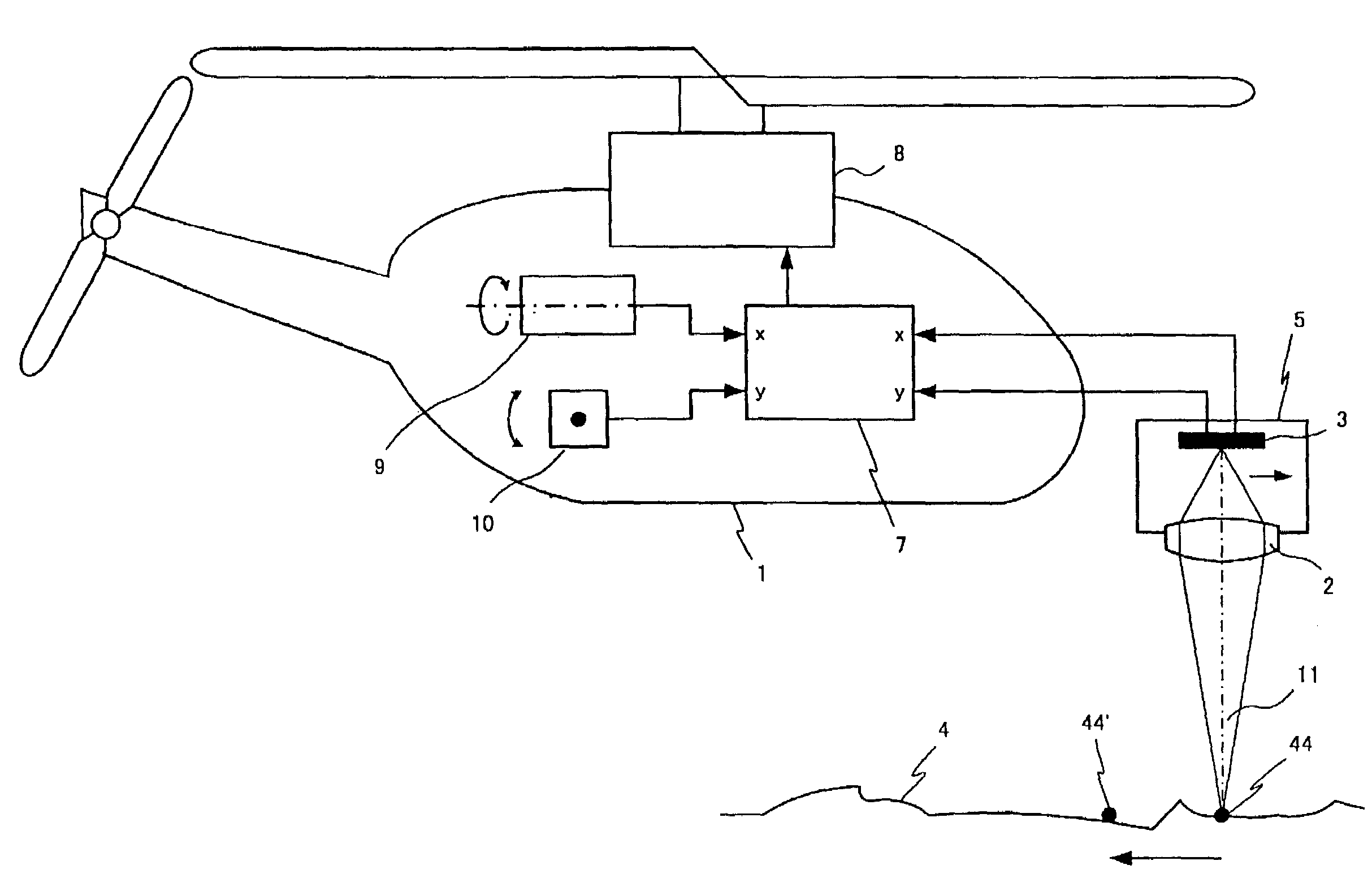
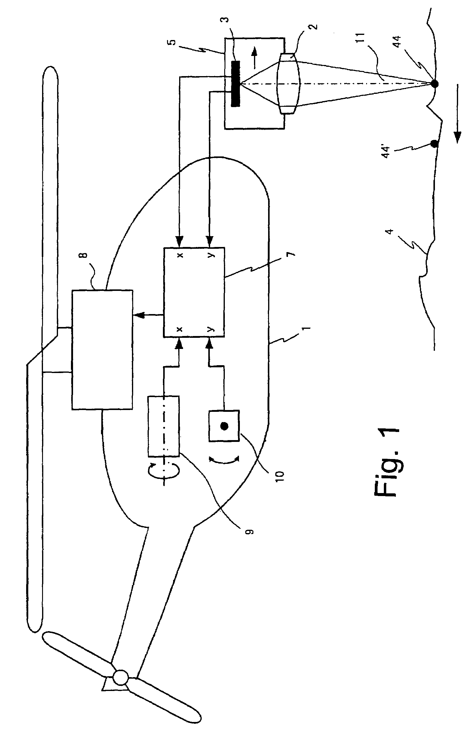
[0088]FIG. 1 shows a first embodiment example for measuring and stabilising the horizontal movements of a helicopter 1. The lens 2 acts as objective lens and projects a visible section of the ground 4 onto the optical shift sensor 3 having an integrated analysing unit, on the same chip. During a forward movement, ground spot 44 migrates optically to the position 44′, and accordingly, its image on the sensor 3 is shifted. The sensor outputs the incremental measurement values of the shift in two coordinates (x and y). If the line of sight, as indicated, is downwards, information concerning the flight velocity with respect to ground in both components forward direction and lateral direction is obtained.

[0089]These measurement values may be used for stabilising the flight path or a still-standing hovering flight. To this end, the feedback-control electronics 7 is, at its input side, connected to the optical measurement signals, and at its output side outputs control values for controlli...


PUM


Abstract

In order to measure the movement of a vehicle, especially an aircraft, an imaging optical system 2 which is to be positioned on the vehicle is used to detect an image of the environment 4, and an optoelectronic shift sensor 3 chip of the type comprising an inherent evaluation unit is used to measure any shift of the image from structures thereof. The shift sensor is equal or similar to the sensor used on an optical mouse. The sensor is positioned in such a way that infinite objects are focused. The measuring signal is evaluated to indicate movements and / or the position of the aircraft. The inventive system can also be used to measure distances e.g. in order to control the flight altitude. The invention further relates to methods for automatically controlling particularly a hovering flight by means of a control loop using optical flow measurement.

Description

RELATED APPLICATION[0001]This is a continuation of International Application PCT / IB203 / 004126, with an international filing date of Sep. 23, 2003.FIELD OF THE INVENTION[0002]The invention relates to an apparatus and a process for measuring motion-related measurands like velocity and / or position of a machine-controllable vehicle in at least one of its six degrees of freedom, wherein the term “vehicle” may include airbone objects, using optical sensor technology; furthermore especially a use as stabilising system for controlling unmanned or manned airborne objects. The purpose of such a stabilising is to substantially simplify or to completely take over the control.[0003]Such stabilising is especially important for remote controlled helicopters, since their control is difficult, and only possible by trained pilots. In case of the helicopter, the control may especially include one or both horizontal components of flight motion.[0004]A further possible field of application of the invent...

Claims


Application Information

Patent Timeline
Patent Type & Authority Patents(United States)
IPC IPC(8): G01C23/00A63H27/04A63H30/04B64C27/00B64C27/58G01P3/36G01P3/38G01P3/68G01P3/80G01S5/16G01S11/12G05D1/04G05D1/08
CPCA63H27/04A63H27/12A63H30/04G01P3/36G05D1/0858G01P3/806G01S5/16G01S11/12G05D1/042G01P3/68
Inventor REICH, STEFAN
Owner IRON BIRD LLC
Why Eureka
Try Eureka