Eureka AIR delivers breakthrough ideas for toughest innovation challenges, trusted by R&D personnel around the world.

View around flow indicator

a flow indicator and view technology, applied in the field of view around flow indicators, can solve the problems of mass waste, personal injury, death, etc., and achieve the effects of easy manufacture, low stall speed, and improved coupling of the cylinder

Active Publication Date: 2008-07-22
DONEHUE WADE L
View PDF14 Cites 10 Cited by
  • Summary
  • Abstract
  • Description
  • Claims
  • Application Information

AI Technical Summary

Benefits of technology

"The invention provides an improvement to a view-around flow indicator for an apparatus used to measure the flow of fluid through a tube. The improvement involves adding a ring to the turbine wheel and a recess in the tube to allow for better coupling of the cylinder to the turbine wheel. This avoids unnecessary restrictions on the flow path and allows for larger magnets to be used. Additionally, the invention provides a method for flowing fluid through a diverging section of the tube to create lower pressure drop than the prior art process. These improvements provide a more accurate and reliable indication of fluid flow through the apparatus."

Problems solved by technology

In the plant setting, a failure to make the correct determination can result in waste and / or destruction on a massive scale, personal injury, and death.

Method used


Image

  • View around flow indicator
  • View around flow indicator
  • View around flow indicator

Examples


Embodiment Construction

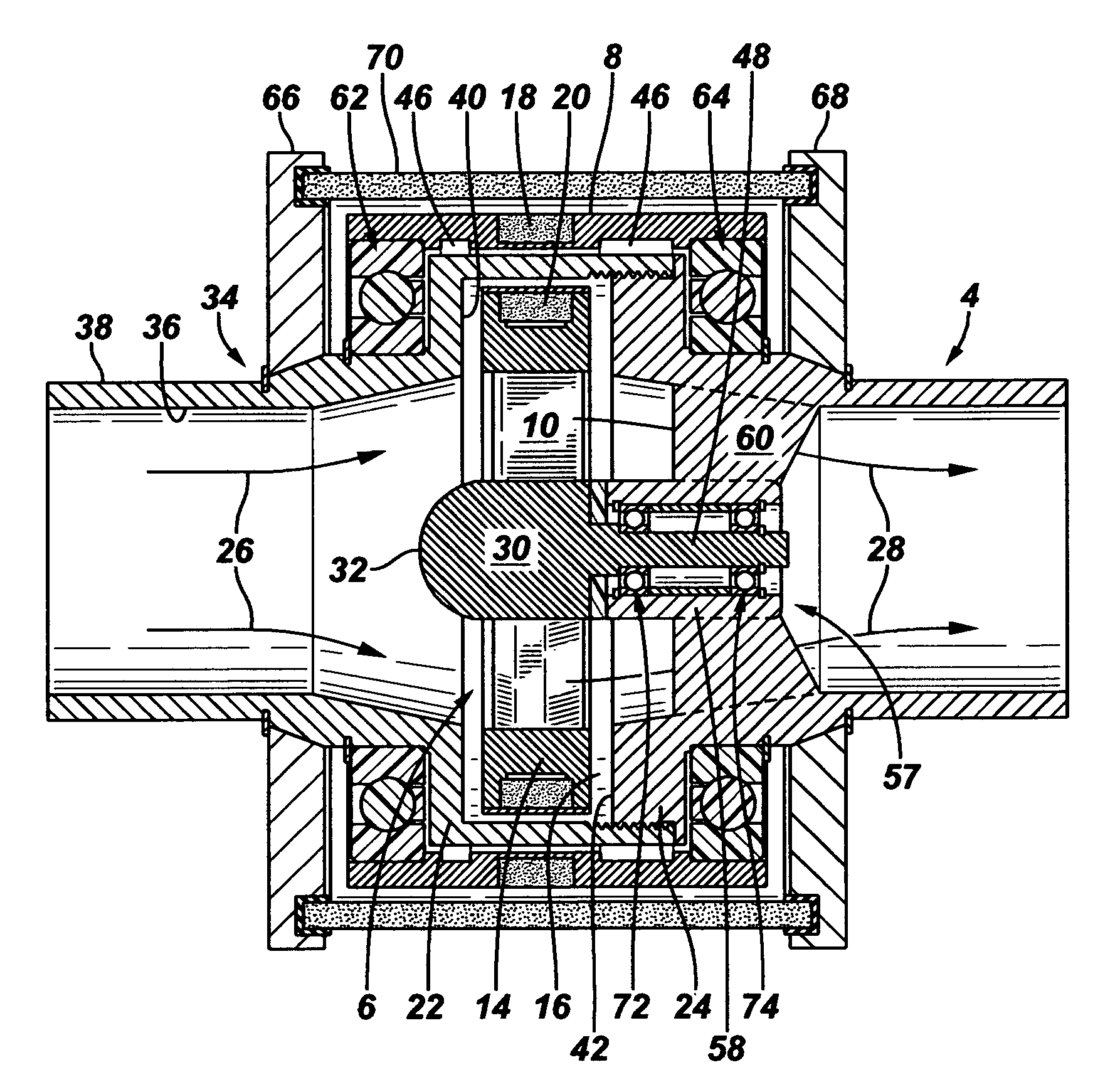
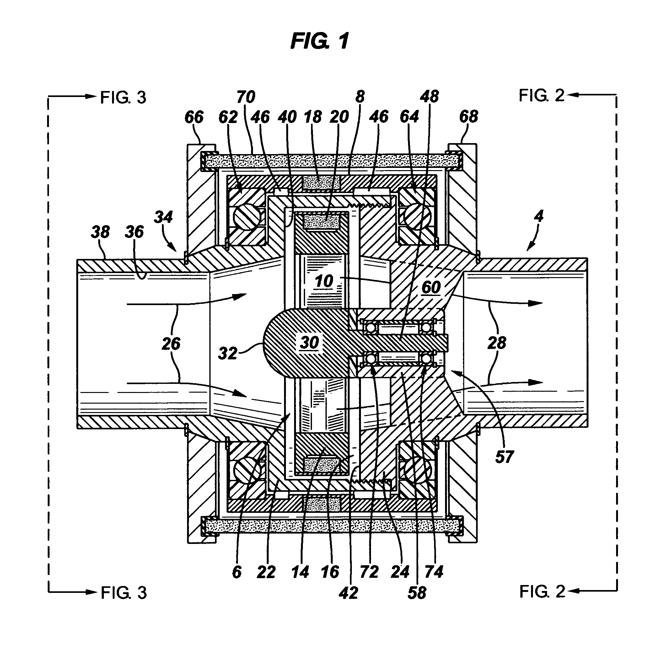
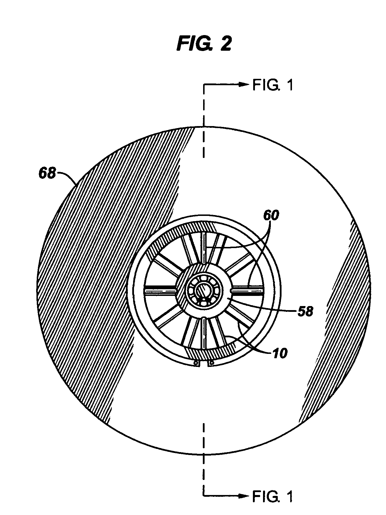
[0018]One embodiment of the invention provides an improved view-around flow indicator 2 (FIG. 6). The apparatus comprises a tube 4, a turbine wheel 6 in the tube, and a cylinder 8 mounted outside of the tube which is magnetically coupled to the turbine wheel as so to give an indication of flow in the tube. The tube defines a flow path for fluid flow as indicated by the arrows. The turbine wheel is mounted in the tube for rotation alongside an inside wall of the tube and is provided with a plurality of turbine blades 10. The cylinder is mounted outside the tube for rotation alongside an outside wall of the tube and is magnetically coupled to the turbine wheel through the sidewall of the tube so that rotation of the turbine wheel causes rotation of the cylinder. A visually observable pattern 12 (FIG. 6) is provided on an outside surface of the cylinder so that rotation of the cylinder can be visually ascertained. The improvement comprises a ring 14 mounted peripherally around pluralit...


PUM


Abstract

A view around flow indicator comprising a housing, a turbine wheel, a cylinder, and a visually perceptible pattern on the outside surface of the cylinder is disclosed. The housing has an inside surface defining a flow path. The inside surface of the housing forms a generally circumferentially extending annular recess. The turbine wheel comprises a hub positioned on the longitudinal axis, a ring positioned in the annular recess, a plurality of radially extending turbine blades connecting the hub with the ring, and plurality of magnets carried by the ring. The cylinder is mounted on an outside surface of the housing for rotation around the longitudinal axis of the flow path. The cylinder carries a plurality of magnets which are magnetically coupled to the plurality of magnets carried by the ring. The visually observable pattern on the outside surface of the cylinder permits rotation of the cylinder to be visually ascertained.

Description

FIELD OF THE INVENTION[0001]In one aspect, this invention relates to an improved device to provide an external visual indication of fluid flow within an opaque pipe.BACKGROUND OF THE INVENTION[0002]Determining whether fluid is flowing through a hard-walled opaque pipe can be important for a number of reasons. In the plant setting, a failure to make the correct determination can result in waste and / or destruction on a massive scale, personal injury, and death.[0003]A device which enables one to visually ascertain from a distance whether fluid is flowing within pipe is described in my U.S. Pat. No. 6,526,907, issued Mar. 4, 2003. The disclosure of this patent is incorporated by reference herein. The patent discloses a flow indicating device which is highly visible, easy to read, and is viewable from any location around the pipe.[0004]While this device is a noteworthy advance in the art, it has been possible to improve it in several areas, primarily from the standpoints of providing a ...

Claims


Application Information

Patent Timeline
Patent Type & Authority Patents(United States)
IPC IPC(8): G01F1/115
CPCG01F1/115G01F15/14G01F15/06Y10S116/07Y10T137/8326
Inventor DONEHUE, WADE L.
Owner DONEHUE WADE L
Why Eureka
Eureka Blog
Learn More