Polymeric acetabular cup

a polymer and acetabular cup technology, applied in the field of orthopedic prosthesis, can solve the problems of difficult adhesion of cement or other fixation material to the acetabular cup, loosening of the acetabular cup from the bone, and degeneration of the hip join

Inactive Publication Date: 2008-07-22
ORTHO DEV CORP
View PDF22 Cites 3 Cited by
  • Summary
  • Abstract
  • Description
  • Claims
  • Application Information

AI Technical Summary

Problems solved by technology

Over time, degeneration of the hip joint is a relatively common problem that may manifest itself in various forms.
This design is disadvantageous because the surface segments formed by the grooves contain sharp edges and corners and are shaped in such a manner so as to create stress risers between the acetabular cup and the fixation material, which may cause cracking in the cement or other fixation material loosening the acetabular cup from the bone.
Further, the grooves contain sidewalls that do not taper making it difficult for the cement or other fixation material to adhere to the acetabular cup.
The resulting configuration of the acetabular cup contains several raised segments that are sharp and have potential to cause stress risers, causing the acetabular cup to crack the surrounding cement or fixation material, thus loosening the acetabular cup from the bone.
Similar to the '727 patent granted to Otto et al., the grooves of this patent lack a tapered sidewall and further lack an undercut surface that functions to enhance fixation, making it difficult to secure the acetabular cup within the bone.
It is noteworthy that none of the prior art known to applicant provides a prosthetic implant capable of being directly implanted into a socket portion of a ball and socket joint that comprises a multi-directional and multi-planar recessed channel having rounded edges to decrease the occurrence of stress risers, and tapered walls that create an undercut surface for enhancing fixation between said implant and the bone cement or other fixation material.

Method used


Image

  • Polymeric acetabular cup
  • Polymeric acetabular cup
  • Polymeric acetabular cup

Examples


Embodiment Construction

[0032]For the purposes of promoting an understanding of the principles in accordance with the disclosure, reference will now be made to the embodiments illustrated in the drawings and specific language will be used to describe the same. It will nevertheless be understood that no limitation of the scope of the disclosure is thereby intended. Any alterations and further modifications of the inventive features illustrated herein, and any additional applications of the principles of the disclosure as illustrated herein, which would normally occur to one skilled in the relevant art and having possession of this disclosure, are to be considered within the scope of the disclosure claimed.

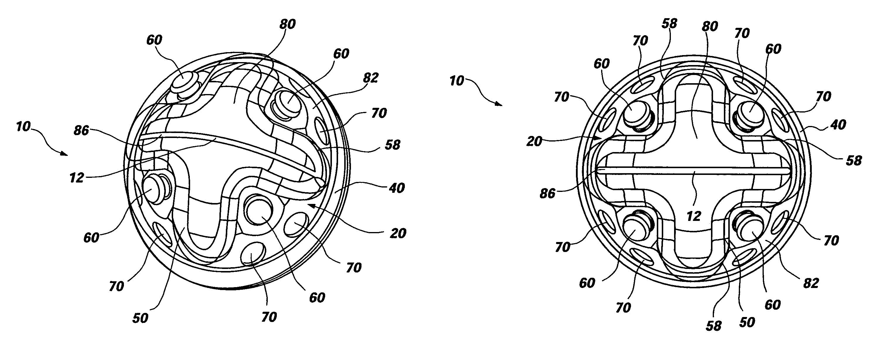
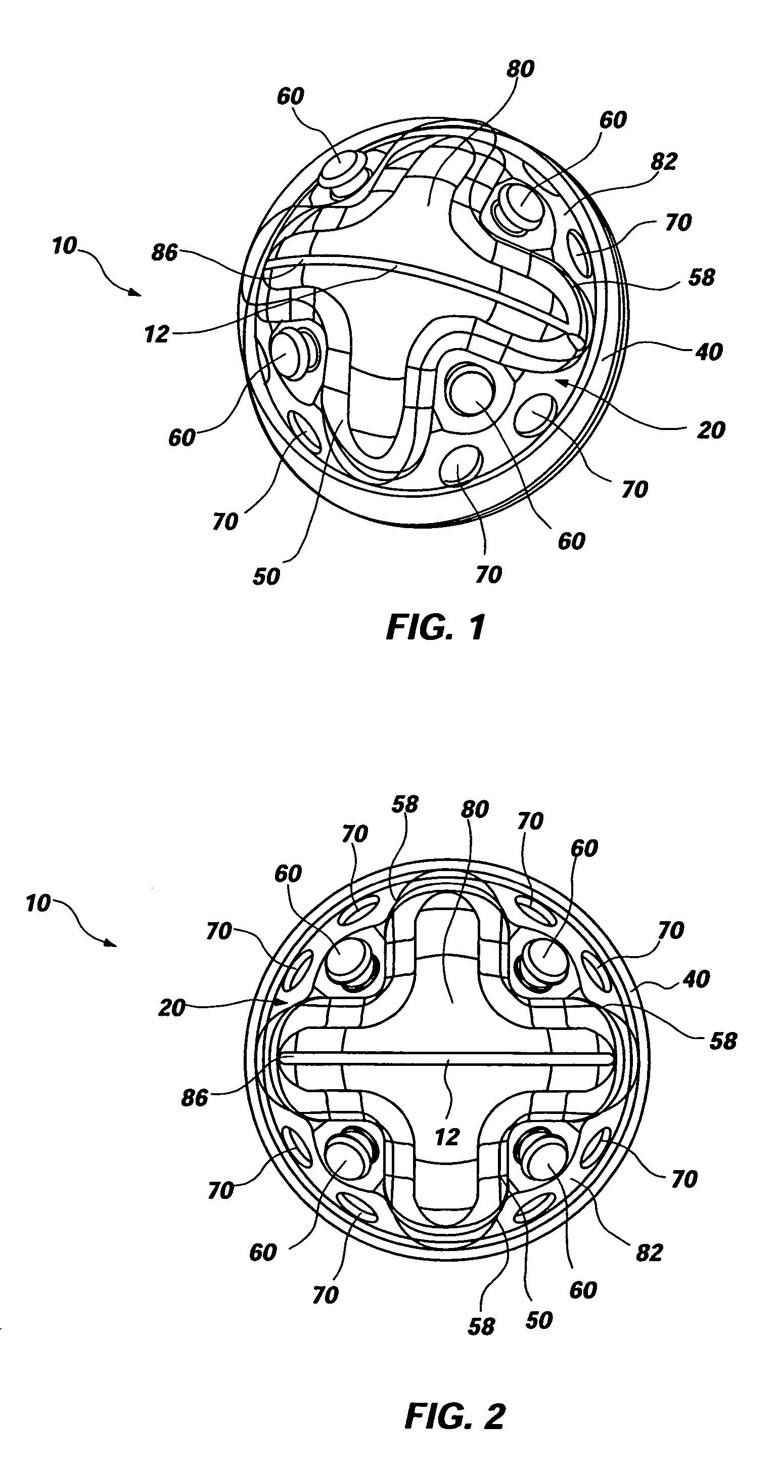
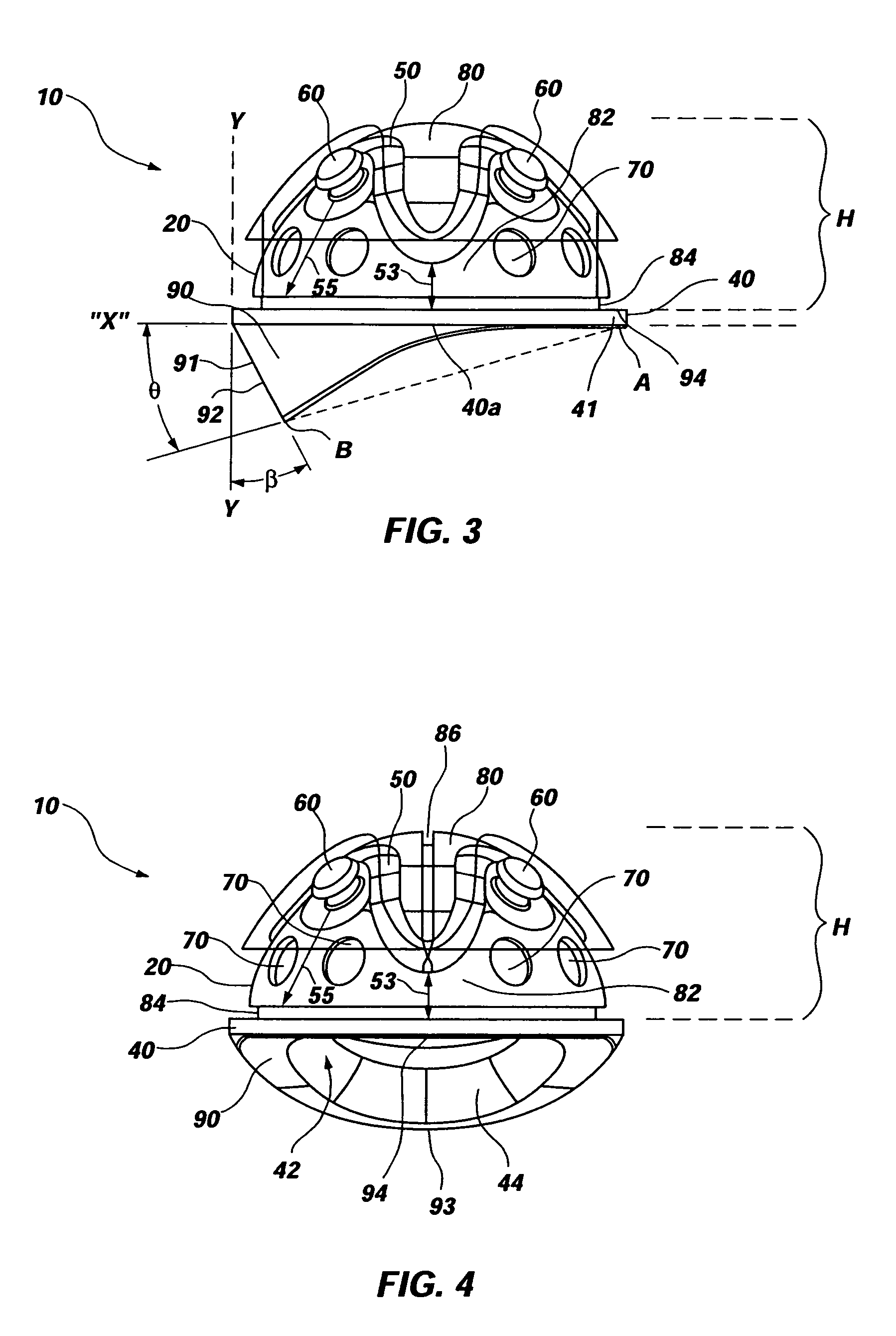
[0033]Applicants have discovered that fixation of an acetabular cup member directly into a socket of a pelvis may be greatly enhanced by utilizing a uniquely designed acetabular cup member having, among other features, a recessed channel, formed with or without an undercut surface, that permits a fixation ...


PUM


Abstract

An orthopedic prosthesis comprising a polymeric cup member for use in a ball and socket joint is disclosed. The cup member may include several advantageous features such as a multi-directional and multi-planar channel having an undercut area that provides a mechanical lock between the cup member and a fixation material for enhanced fixation. The cup member may further comprise a plurality of spacers for ensuring an even mantle of fixation material between the cup member and the bone, a series of divots for enhancing fixation, a locating feature that permits a physician to visualize and locate the cup member in the socket of the patient's bone on appropriate medical equipment, and a lead-in chamfer located between a terminal edge and an interior surface of the cup member. Further, the terminal edge of the cup member may comprise a planar rim or may alternatively comprise a hood located distally from said terminal edge.

Description

CROSS-REFERENCE TO RELATED APPLICATIONS[0001]This application is a continuation-in-part of PCT Application No. PCT / US2004 / 002863, entitled “POLYMERIC ACETABULAR CUP,” filed in the United States Patent Office and having an international filing date of Feb. 2, 2004, which claimed the benefit of U.S. Provisional Application No. 60 / 444,006, filed Jan. 31, 2003 entitled “POLYMERIC ACETABULAR CUP,” both of which are hereby incorporated by reference herein in their entireties, including but not limited to those portions that specifically appear hereinafter, the incorporation by reference being made with the following exception: In the event that any portion of the above-referenced applications is inconsistent with this application, this application supercedes said above-referenced portion of said applications.STATEMENT REGARDING FEDERALLY SPONSORED RESEARCH OR DEVELOPMENT[0002]Not Applicable.BACKGROUND[0003]1. The Field of the Invention.[0004]The present disclosure relates generally to an ...

Claims


Application Information

Patent Timeline
Patent Type & Authority Patents(United States)
IPC IPC(8): A61F2/30A61F2/36A61FA61F2/00A61F2/32A61F2/34A61F2/46
CPCA61F2/30724A61F2/34A61F2/30771A61F2250/0098A61F2002/3008A61F2002/30121A61F2002/30136A61F2002/30159A61F2002/30497A61F2002/30619A61F2002/30805A61F2002/3081A61F2002/3082A61F2002/30822A61F2002/30823A61F2002/30827A61F2002/30831A61F2002/30894A61F2002/30957A61F2002/3429A61F2002/3443A61F2002/4631A61F2220/0025A61F2230/0004A61F2230/0006A61F2230/0028A61F2250/0097A61F2002/30495A61F2002/30617
Inventor JONES, SCOTT A.PETERMAN, MARC M.
Owner ORTHO DEV CORP
Why Eureka
Try Eureka