Optical finger print input device for mobile apparatus

a fingerprint input and mobile technology, applied in the field of optical fingerprint input devices, can solve the problems of difficult to distinguish between oil information and fingerprint information difficult to apply to mobile devices, etc., to achieve the effect of avoiding distortion of fingerprint images, removing oil and sweat, and convenient application

Inactive Publication Date: 2008-07-22
HANSL
View PDF6 Cites 5 Cited by
  • Summary
  • Abstract
  • Description
  • Claims
  • Application Information

AI Technical Summary

Benefits of technology

[0008]The present invention is disclosed to solve the aforementioned drawbacks and it is an object of the present invention to provide an optical fingerprint input device for a mobile apparatus configured to be thinned in thickness thereof and to be capable of removing oil and sweat therefrom such that distortion of fingerprint images can be avoided for an easy application to a mobile apparatus.

Problems solved by technology

However, there is a drawback in the optical fingerprint input apparatus thus described according to the prior art in that miniaturization of the apparatus is restricted by the thickness of the lens, making it difficult to be integrated with other apparatus.
However there arises another drawback in that an angle of an inclined surface becomes larger as the thickness of prism is thinned to proportionally produce a worsened trapezoidal distortion of the fingerprint images, making it impossible to be applied to mobile apparatus where a thin-light-miniaturized look is valued high as in cellular phones.
There is still another drawback in that oil from a human's hand or face can stain a fingerprint contact region of an optical fingerprint input apparatus when the apparatus is applied to a cellular phone, making it difficult to distinguish between oil information and fingerprint information and to verify fingerprints.

Method used


Image

  • Optical finger print input device for mobile apparatus
  • Optical finger print input device for mobile apparatus
  • Optical finger print input device for mobile apparatus

Examples


first embodiment

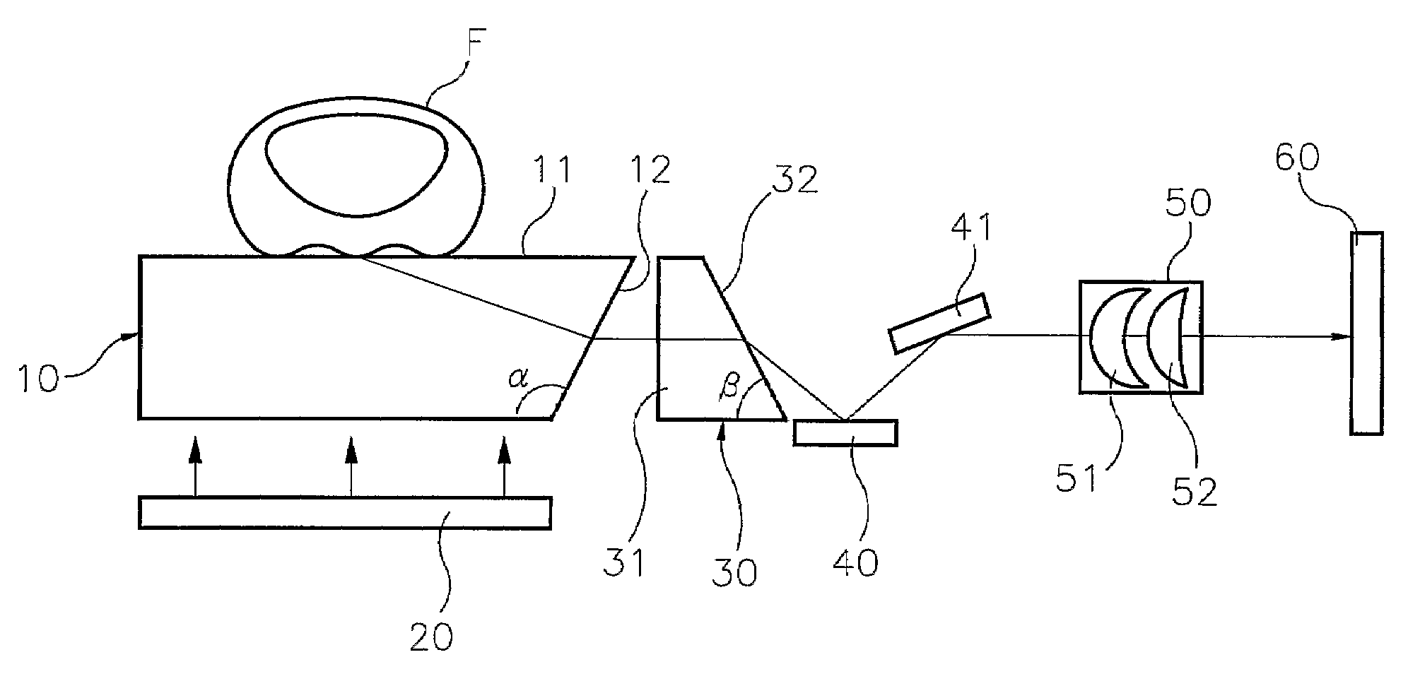
[0029]Referring to FIG. 2, the optical fingerprint input device for a mobile apparatus includes a fingerprint input member (10), a light source (20), a distortion correcting member (30), first and second reflecting members (40, 41), an image forming unit (50) and an image sensor (60).

[0030]The fingerprint input member (10) made of a thin plate-shaped light-penetrative material such as glass, plastic or the like, is formed thereon with an incident surface (11) for receiving fingerprint images of a finger (F) and an inclined surface (12) disposed at one side thereof contacting the incident surface (11) with a first set-up angle (α). The first set-up angle (α) at the inclined surface (12) of the fingerprint input member (10) is so set up as to display only a genuine fingerprint image devoid of sweat, water, oil or the like.

[0031]The light source (20) serves to evenly illuminate beam lights toward the incident surface (11) of the fingerprint input member (10). A back light module used f...

second embodiment

[0062]Meanwhile, referring to FIGS. 12a and 12b, and FIGS. 13a and 13b, an optical fingerprint contact device for a mobile apparatus according to a second embodiment of the present invention is illustrated, which is an application of the optical fingerprint input device for a mobile apparatus according to the first embodiment of the present invention illustrated in FIG. 2.

[0063]A camera function of a cellular phone and a fingerprint input function of a fingerprint input device are commonly utilized via a single image sensor (60) in the optical fingerprint contact device for a mobile apparatus according to the second embodiment of the present invention.

[0064]In other words, the optical fingerprint contact device according to the second embodiment of the present invention further includes, between the image forming unit (50) and the image sensor (60), an image input module (100) for a camera phone, and moving means for moving the image input module (100) according to a user's choice b...

third embodiment

[0067]Referring now to FIGS. 14a and 14b, an optical fingerprint contact device for a mobile apparatus according to a third embodiment of the present invention is disclosed.

[0068]As in the second embodiment illustrated in FIGS. 12 and 13, a camera function of a cellular phone and a fingerprint input function of a fingerprint input device are commonly utilized via a single image sensor (60) in the optical fingerprint contact device for a mobile apparatus according to the third embodiment of the present invention. The only difference is that a reflecting member (210) for a camera phone and a lens module (220) for a camera phone are separately provided, where the lens module (220) is fixed while the reflecting member (210) can be moved by moving means.

[0069]The foregoing description of the preferred embodiments of the present invention has been presented for the purpose of illustration and description. It is not intended to be exhaustive or to limit the invention to the precise form di...


PUM


Abstract

An optical fingerprint image input device for a mobile apparatus includes: a plate-shaped fingerprint contact member; a distortion correcting member for correcting distortions; light sources disposed at both sides of the fingerprint contact member, other than an inclined surface or a back light source in a liquid crystal display element; focusing means disposed at an inclined surface side of the distortion correcting member; and an image sensor. In other words, the fingerprint contact member and the distortion correcting member having respective set-up inclined angles are disposed to discern sweat, water or oil and to correct a trapezoidal distortion which is a disadvantage that occurs when a thin fingerprint contact medium is used, and to form a lens system comprised of a cylindrical lens and a spherical lens for adjustment of a ratio of transversal to longitudinal widths of an image.

Description

FIELD OF THE INVENTION[0001]The present invention relates to an optical fingerprint input device capable of being applied to a mobile apparatus such as a cellular phone and the like and, more particularly, to a thin optical fingerprint input device capable of obtaining high-resolution fingerprint information without any image distortion.BACKGROUND OF THE INVENTION[0002]In general, there are three methods of obtaining fingerprint information from human beings, namely, indirect method, optical method and non-optical method. The indirect method involves the use of scanners or cameras for scanning or photographing fingerprints printed on a paper, and the non-optical method utilizes the principle of electric field.[0003]The most efficient and common method is the optical method. As shown in FIG. 1, an apparatus for optically inputting fingerprints includes a light source (1) for illuminating light on a fingerprint region, a diffusing plate (2) for diffusing light generated from the light...

Claims


Application Information

Patent Timeline
Patent Type & Authority Patents(United States)
IPC IPC(8): G06K9/74G06K9/00
CPCG06K9/00046G06V40/1324H04W12/06G06F18/00
Inventor KIM, HYUNSEO, YOUNG JINAHN, JONG WOOLEE, SEUNG MINHONG, SA HYANGLEE, TAE HUNKWAK, BYUNG KEE
Owner HANSL
Why Eureka
Try Eureka