Programmable phase interpolator adjustment for ideal data eye sampling

a phase interpolator and phase shift technology, applied in the field of phase shifting circuits, can solve the problems of data sampling process errors and increase bit-error rates

Inactive Publication Date: 2008-07-22
INTEL CORP
View PDF7 Cites 29 Cited by
  • Summary
  • Abstract
  • Description
  • Claims
  • Application Information

AI Technical Summary

Problems solved by technology

If this position is not optimum, bit-error rates will increase, which, in turn, will cause errors to be induced during the data sampling process.

Method used


Image

  • Programmable phase interpolator adjustment for ideal data eye sampling
  • Programmable phase interpolator adjustment for ideal data eye sampling
  • Programmable phase interpolator adjustment for ideal data eye sampling

Examples


first embodiment

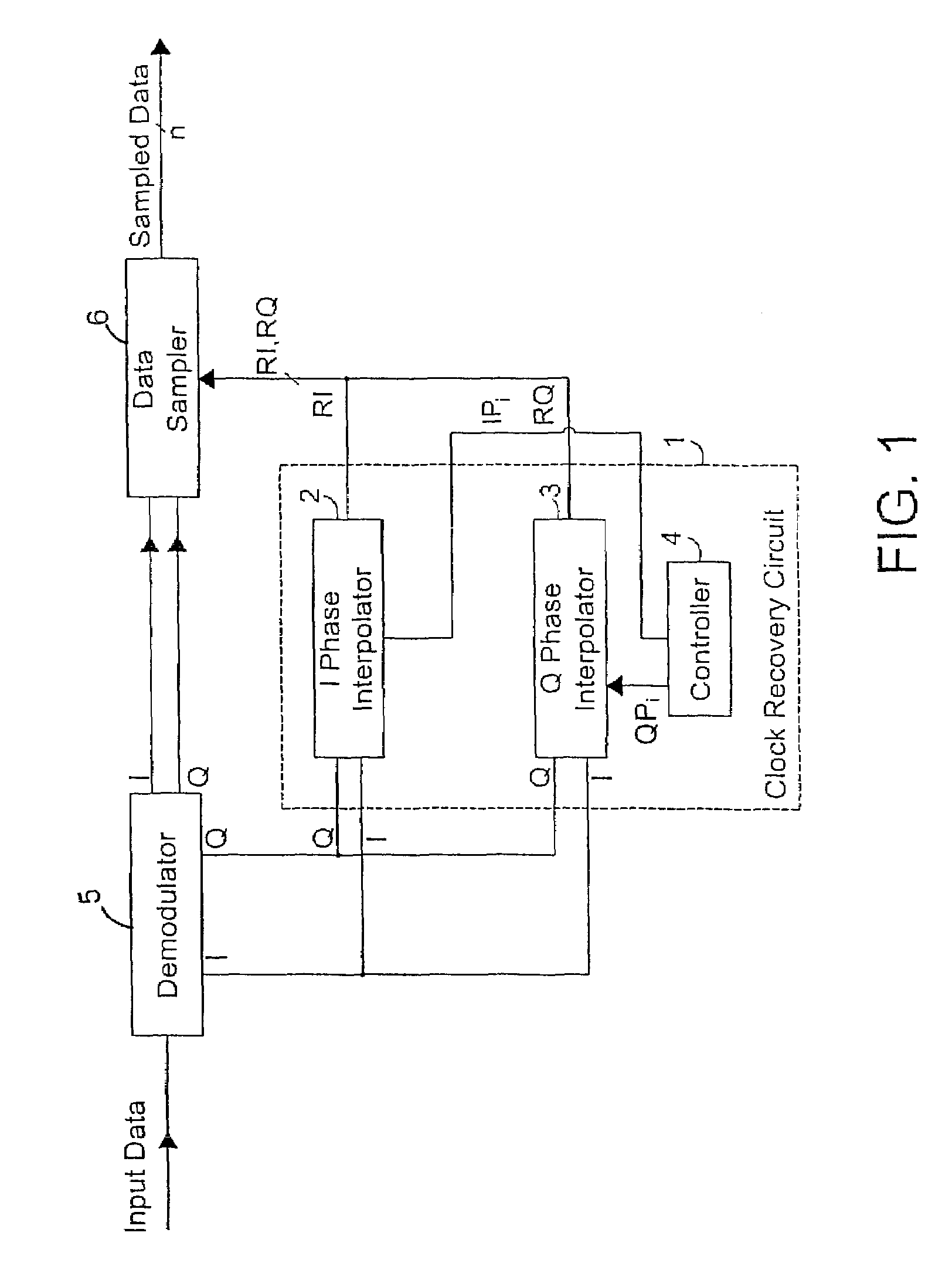
[0021]A clock signal recovery circuit in accordance with. the present invention may be used to generate clock phase information for controlling the sampling of data. The data may be received or otherwise conveyed in any one of a variety of communications or high-speed signaling systems, including but not limited to optical, wireless, and wireline systems. If the data received in these systems are not transmitted with a dedicated clock signal, the clock signal recovery circuit may be used to recover clock information from the received data using known techniques. The clock information is then used as a basis for converting the data into digital signals through sampling. In an alternative embodiment, the clock information is recovered from a master clock.

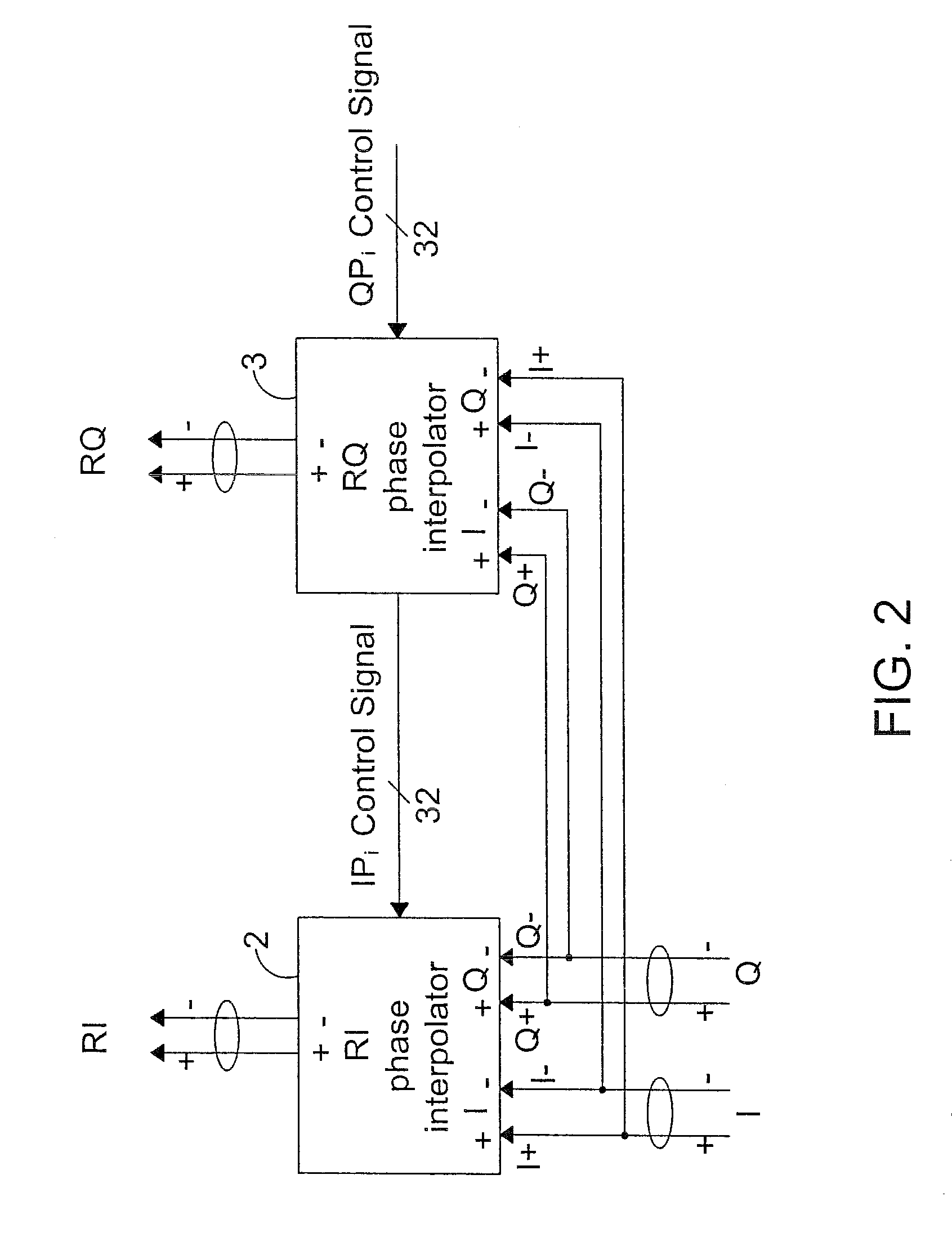
[0022]Referring to FIG. 1, the clock signal recovery circuit 1 includes a pair of phase interpolators 2 and 3 which respectively shift phases of quadrature (Q) and in-phase (I) signals based on control information (IPi, QPi) generated...

second embodiment

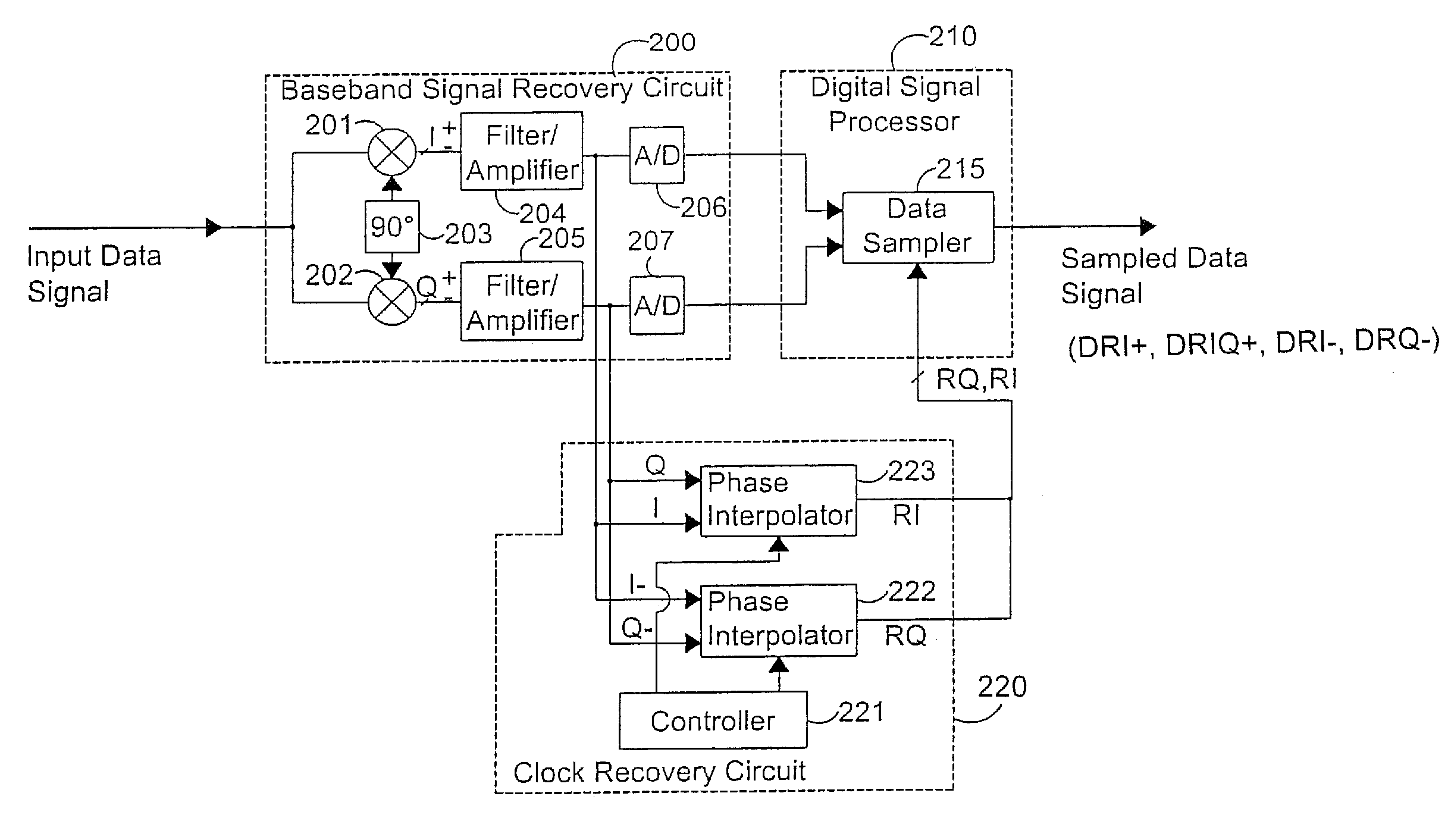
[0057]A recovery circuit in accordance with the present invention may also be used to generate clock phase information for controlling the sampling of data. In this embodiment, however, the clock signal recovery circuit generates the clock phase information using a master clock instead of deriving the phase information from the received data. More specifically, the master clock generates I and Q reference signals, which are at a predetermined fraction and preferably half the frequency of the data rate. These signals may have any arbitrary phase with respect to the data and as such are not related in phase to the data. Phase interpolation is required to generate the recovered clock phases, RI and RQ. This clock information is then used as a basis for converting the data into digital signals through sampling.

[0058]FIG. 11 shows an example of the recovery circuit of the second embodiment. This circuit includes an analog section and a digital processing section. The analog section inclu...


PUM


Abstract

A clock recovery circuit includes a demodulator which generates in-phase and quadrature signals from a data signal and a phase adjuster which adjusts a phase of the quadrature signal independently from a phase of the in-phase clock signal. The phase adjustment causes a non-orthogonal relationship to exist between the phases of the quadrature and in-phase signals. The independent phase adjustment may be dynamically performed or may be performed in fixed increments to achieve a predetermined level of performance. In one application, the adjusted quadrature phase signal serves as a clock signal for controlling sampling of the data signal.

Description

FIELD[0001]This invention generally relates to phase-shifting circuits and their applications.BACKGROUND OF THE INVENTION[0002]High-speed signaling systems often transmit data without a dedicated clock. Digital receivers must therefore have a reference clock or recover the clock from the data itself. This timing information is used to control a variety of functions in the receiver including the sampling process used to convert received data into digital signals.[0003]A variety of recovery circuits have been proposed for extracting clock information from received data. A variety of supplied methods for the reference clock also exists. In general, due to issues with spectral purity, the reference clock will be provided at a lower rate and multiplied in frequency with an internal clock multiplication circuitry. These circuits often use an interpolator to set the phase of the recovered clock during sampling. From a performance standpoint, the location of the clock phase relative to an e...

Claims


Application Information

Patent Timeline
Patent Type & Authority Patents(United States)
IPC IPC(8): H04L7/00H03L7/081H03L7/091H03L7/099H04L1/00H04L7/033
CPCH03L7/0814H03L7/091H04L7/0334H03L7/0998H04L7/0025
Inventor KOENENKAMP, INGO
Owner INTEL CORP
Why Eureka
Try Eureka