Construction machine and projecting object of the same

a construction machine and projecting object technology, applied in soil shifting machines/dredgers, roofs, transportation and packaging, etc., can solve the problems of increasing the total weight of the vehicle, reducing the operability of the vehicle, and reducing work efficiency, so as to achieve low cost, facilitate production, and avoid interference with the components of the construction machine

Inactive Publication Date: 2008-07-29
KOMATSU LTD
View PDF12 Cites 2 Cited by
  • Summary
  • Abstract
  • Description
  • Claims
  • Application Information

AI Technical Summary

Benefits of technology

[0007]The present invention is directed to overcoming the foregoing problems and a primary object of the invention is therefore to provide a construction machine and a projecting member thereof, which carry out restriction of deformation of an operator's cab in the event of tumbling of the construction machine without causing increased weight and decreased visibility and which can be manufactured at low cost.
[0014]According to the first and second aspects, in the event of tumbling, the construction machine is supported with the virtual plane being in contact with the ground, which virtual plane is defined by the respect ends of the revolving superstructure frame, work implement and counterweight or the projecting member attached to at least any one of the ends of these members. At that time, an operator's cab space where the operator can work to repair and recover the construction machine can be kept in an inner position of the vehicle body than the virtual plane is located. In this case, the projecting member can be manufactured at lower cost and is less heavier in weight, compared to the conventional cab guard. In addition, since the operator's cab is not enclosed by a cab guard, the visibility of the operator's cab can be increased. As a result, a lightweight structure, which can restrict deformation of the operator's cab in the event of tumbling of the construction machine, can be implemented at low production cost while keeping good visibility for the operator's cab.
[0015]In the construction machine according to the first aspect, the projecting member provided for the counterweight may be an upwardly projecting member disposed on an upper part of the counterweight which upper part faces the rear face of the operator's cab. The upwardly projecting member of this structure facilitates keeping of a large space as the operator's cab space that is located in the inner position than the location of the virtual plane. In addition, since the project area of the construction machine, which is obtained by projection from above, does not increase, the turn radius of the construction machine does not increase. Therefore, the invention can be applied to small-sized and middle-sized construction machines such as small trail radius hydraulic excavators without impairing their operability.
[0020]In the above arrangement, since the projecting member is made of a welded structure, cast part or forged part, it can be universally, easily produced at low cost while the amount of projection such as configuration, thickness and length being adjusted according to the machine. Since the projecting member can be attached by bolting or welding while adjusting its mounting position, the interference with the components of the construction machine can be avoided and the visibility of the construction machine is not impaired. The projecting member can be separately formed without affecting the arrangement of any other components of the construction machine. In addition, since the projecting member is detachable, it can be dismounted according to need, for instance, when the construction machine is put in a delivery vehicle or the like for transportation, so that the transportability of the construction machine is not impaired. This enables it to equip construction machines of basic specification with the projecting member as an option and therefore, the projecting member is universally easily applicable to a wide range of construction machines from small to large sizes.
[0021]To sum up, the invention implements a construction machine and a projecting member thereof, which provide a light-weight inexpensive structure for keeping an operator's cab space that allows the operator to work to repair and recover the construction machine in case of tumbling and which does not impair the visibility of the operator's cab.

Problems solved by technology

For this reason, the cab guard 90 becomes extremely costly and an increase in the weight of the operator's cab leads to an increase in the total weight of the vehicle, resulting in a decrease in the operability of the vehicle.
In addition, the visibility of the operator's cab 85 is interrupted by the cab guard 90, which leads to decreased work efficiency.

Method used


Image

  • Construction machine and projecting object of the same
  • Construction machine and projecting object of the same
  • Construction machine and projecting object of the same

Examples


first embodiment

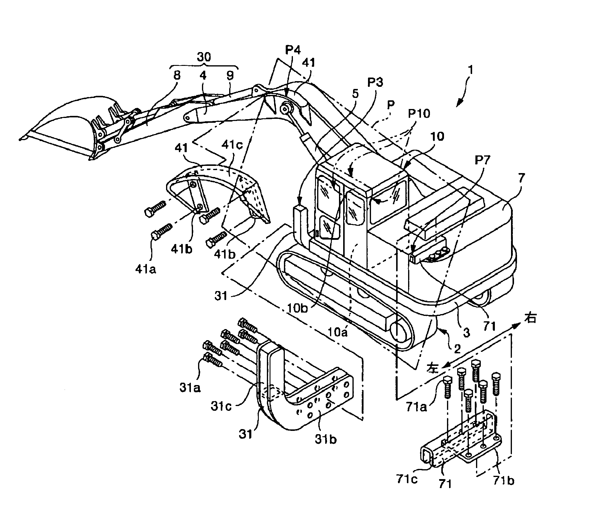
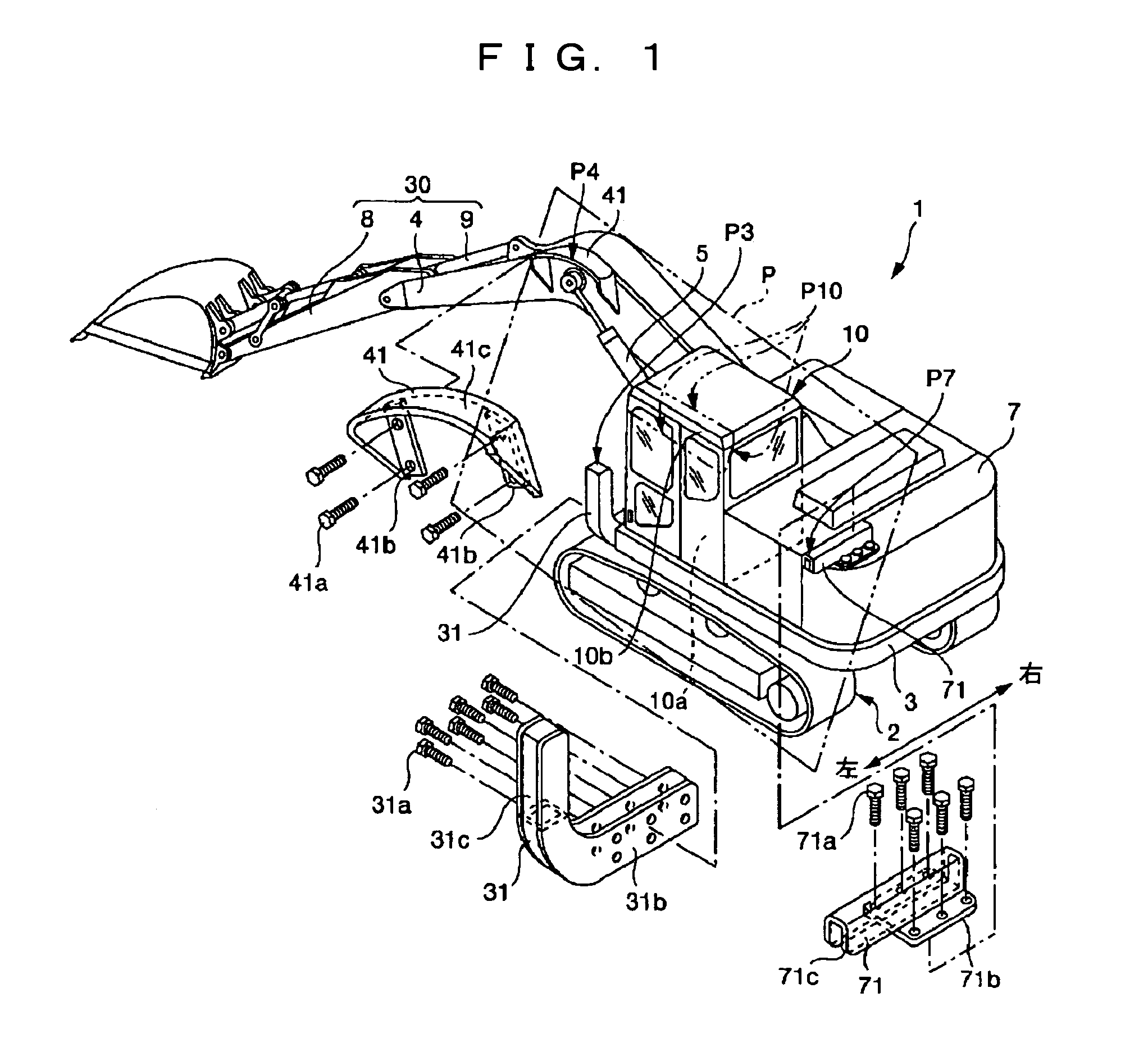
[0040]In the above-described structure, the respective leading ends P3, P4, P7 of the projecting members 31, 41, 71 define a virtual plane P. An operator's cab space 10a, which is located in an inner position of the vehicle body than the location of the intersecting line P10 of the virtual plane P and the operator's cab 10, provides a space large enough to allow the operator to work to repair and recover the construction machine 1 within the operator's cab 10 in case of overturning or tumbling. Although three projecting members 31, 41, 71 are provided in the first embodiment, the number of projecting members is not limited to this. In other words, at least any one of the three projecting members 31, 41, 71 is provided and the virtual plane P is defined by three points that are (i) the end of the revolving superstructure frame 3 which end is located on the side of the operator's cab 10 or the projecting member 31; (ii) the end of the boom 4 or the projecting member 41; and (iii) the ...

second embodiment

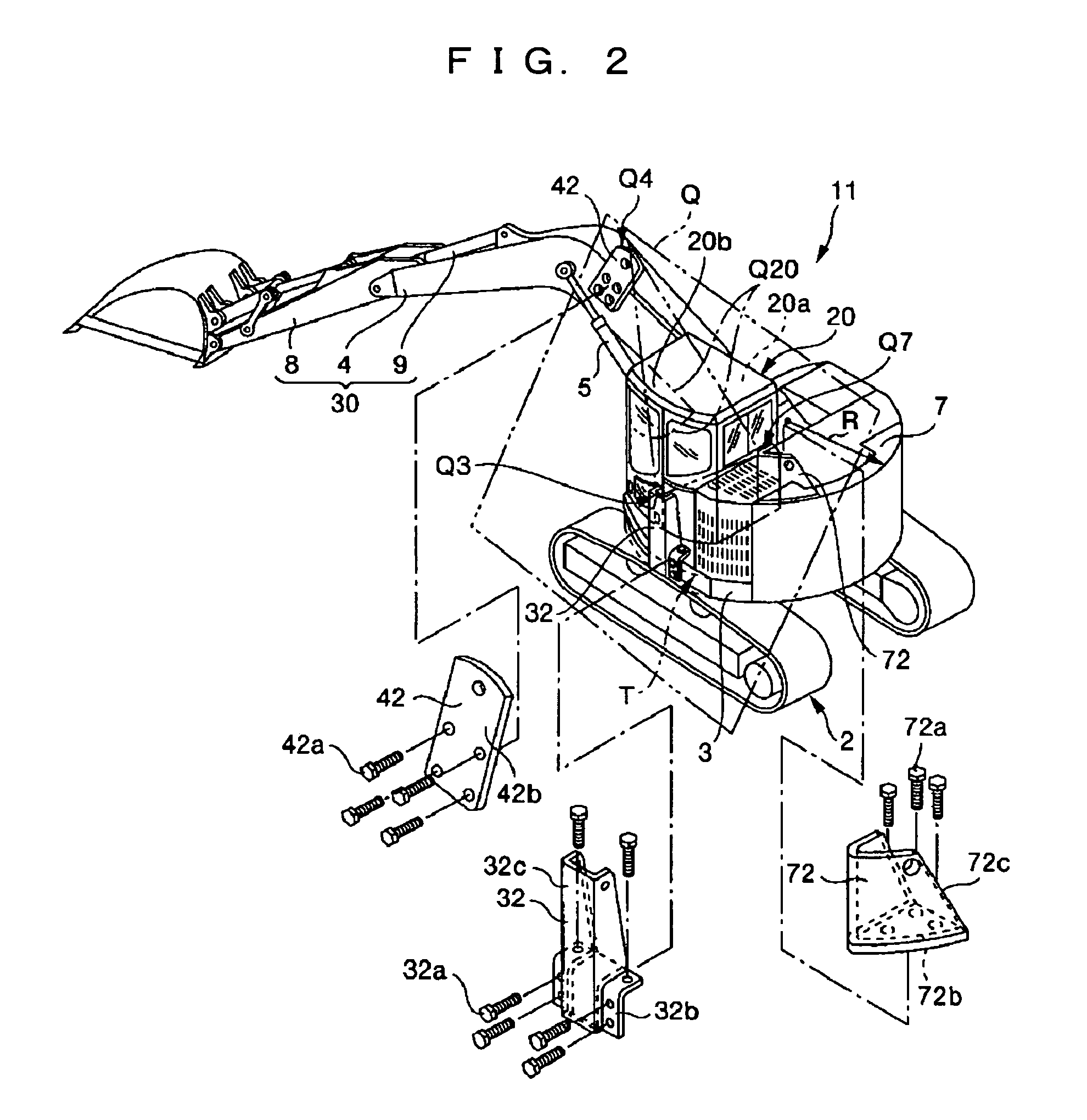
[0043]A projecting member 32 is disposed at an end of the revolving superstructure frame 3 which end is located at a transverse side of the operator's cab 20 (in the second embodiment, the left side of the operator's cab 20). The projecting member 32 is located within the turning radius R of the revolving superstructure frame 3. The projecting member 32 is a welded structure formed such that a supporting member 32c of U-shaped cross-section is welded to a base end member 32b serving as an attaching part, so as to project upward, and such that the base end member 32b is detachably bolted to the revolving superstructure frame 3 with a specified number of bolts 32a. A projecting member 42, which is composed of an upwardly projecting plate 42b, is detachably bolted to the boom 4 with a specified number of bolts 42a. Preferably, the projecting member 42 is disposed in the vicinity of a substantially length-wise mid position that becomes the highest position when the boomerang-like boom 4...

fourth embodiment

[0048]The fourth embodiment is associated with another embodiment of the projecting member disposed at the end of the counterweight 7. To eliminate an influence upon the transportability of the construction machine by avoiding an increase in vehicle width, a projecting member 73, which projects rearward from the counterweight 7, is disposed on the upper face of the counterweight 7 on the same side as the operator's cab. The projecting member 73 is a welded structure composed of a plate-like base end member 73b serving as an attaching part and a supporting member 73c of U-shaped cross-section which is welded to the upper face of the base end member 73b, with the opening end of the member 73c down, such that the supporting member 73c takes the form of a rectangular column extending in a horizontal direction. The projecting member 73 is arranged such that the leading end of the supporting member 73c projects rearward from the counterweight 7 and the base end member 73b is detachably bo...


PUM


Abstract

A construction machine and a projecting member thereof are provided which can be manufactured at low cost and restrict deformation of an operator's cab without impairing visibility in case of tumbling of the construction machine. To this end, there are provided, on a revolving superstructure frame (3), a work implement (30) located on the cross-wise mid position of a front part, a counterweight (7) located at a rear part and an operator's cab located at either the right or left side of the front part. At least one of the revolving superstructure frame, the work implement and the counterweight is provided with a projecting member (31-38) that projects outward. An operator's cab space (10a, 20a) is kept in an inner position of a vehicle body compared to a virtual plane defined by the at least one projecting member and positions where no projecting members are provided.

Description

[0001]This application is a U.S. National Phase Application under 35 USC 371 of International Application PCT / JP2004 / 009271 filed Jun. 24, 2004.TECHNICAL FIELD[0002]The present invention relates to a construction machine and a projecting member thereof, the construction machine being structured such that if the construction machine overturns (“overturn” is defined herein as a turn through approximately 90 degrees) or tumbles (“tumbling” is defined herein as a turn through approximately 180 degrees or more), an operator's cab space can be kept to allow the operator to work to repair and recover the construction machine.BACKGROUND ART[0003]In the field of construction machines, there have been heretofore proposed a variety of means for protecting the operator from overturn or tumbling of a construction machine by restricting or preventing deformation of the operator's cab. One example of such means is disclosed in Japanese Unexamined Published Patent Application No. 2000-230255 (First...

Claims


Application Information

Patent Timeline
Patent Type & Authority Patents(United States)
IPC IPC(8): E02F9/16E02F9/08E02F9/24
CPCE02F9/0808E02F9/24E02F9/16E02F9/08
Inventor MORI, TADASHI
Owner KOMATSU LTD
Why Eureka
Try Eureka