
Image forming apparatus

a technology of image forming apparatus and forming chamber, which is applied in the direction of printing, other printing apparatus, etc., can solve the problems of inability to remove undesirable effects within the ink-jet recording apparatus, inability to achieve normal ink-jet performance, and overflow before the absorbing member, etc., to achieve easy thickening, simple structure, and high viscosity

Active Publication Date: 2008-07-29
RICOH KK
View PDF17 Cites 4 Cited by
  • Summary
  • Abstract
  • Description
  • Claims
  • Application Information

AI Technical Summary

Benefits of technology

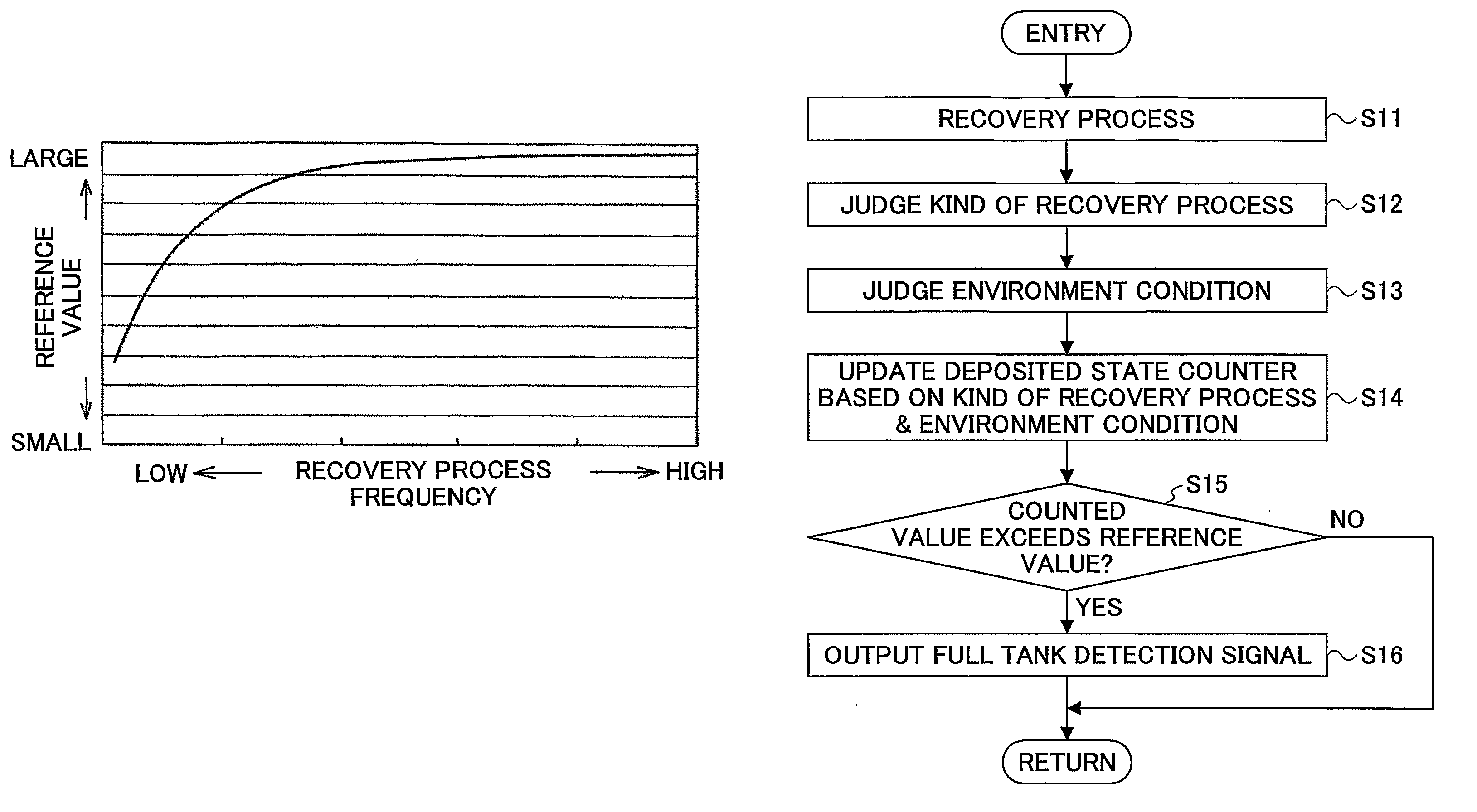
The present invention provides an image forming apparatus that can detect when there is a buildup of waste fluid in a waste tank, even when the recording fluid is thick or viscous. This is done by obtaining a correlation value that is compared to a reference value, and then using judging means to determine if the correlation value exceeds the reference value. This allows for easier detection of waste fluid buildup, which can help to prolong the life of the image forming apparatus and reduce maintenance costs.

Problems solved by technology

The wiping function wipes off the residual recording ink which is adhered on the nozzle surface and causes irregular ink-jet performance unless removed.
If the waste tank becomes full and the waste ink overflows, this ink overflow causes undesirable effects within the ink-jet recording apparatus.
However, unlike dyes, the pigment is water insoluble.
Therefore, if the pigment-based ink is used in combination with the conventional waste tank that is provided with the full tank detection device, there is a problem in that the pigment-based ink may form a deposit in a vicinity of an ink receiving opening in the waste tank and cause an overflow before the absorbing member is used up, because the full tank detection device cannot detect the full waste tank caused by such a deposit.
In addition, since such a deposit prevents the pigment-based ink from evenly filling the entire waste tank, there is a problem in that the pigment-based ink may overflow from the waste tank before the pigment-based ink reaches a sensor of a hardware full tank detection device, particularly when the sensor is located at a position separated from the ink receiving opening in the waste tank.
As a result, there is a problem in that a relatively complex operation is required to calculate the amount of ink consumed every time each of the various kinds of operations described above is carried out, to thereby deteriorate the throughput of the ink-jet recording apparatus.

Method used


Image

  • Image forming apparatus
  • Image forming apparatus
  • Image forming apparatus

Examples


Embodiment Construction

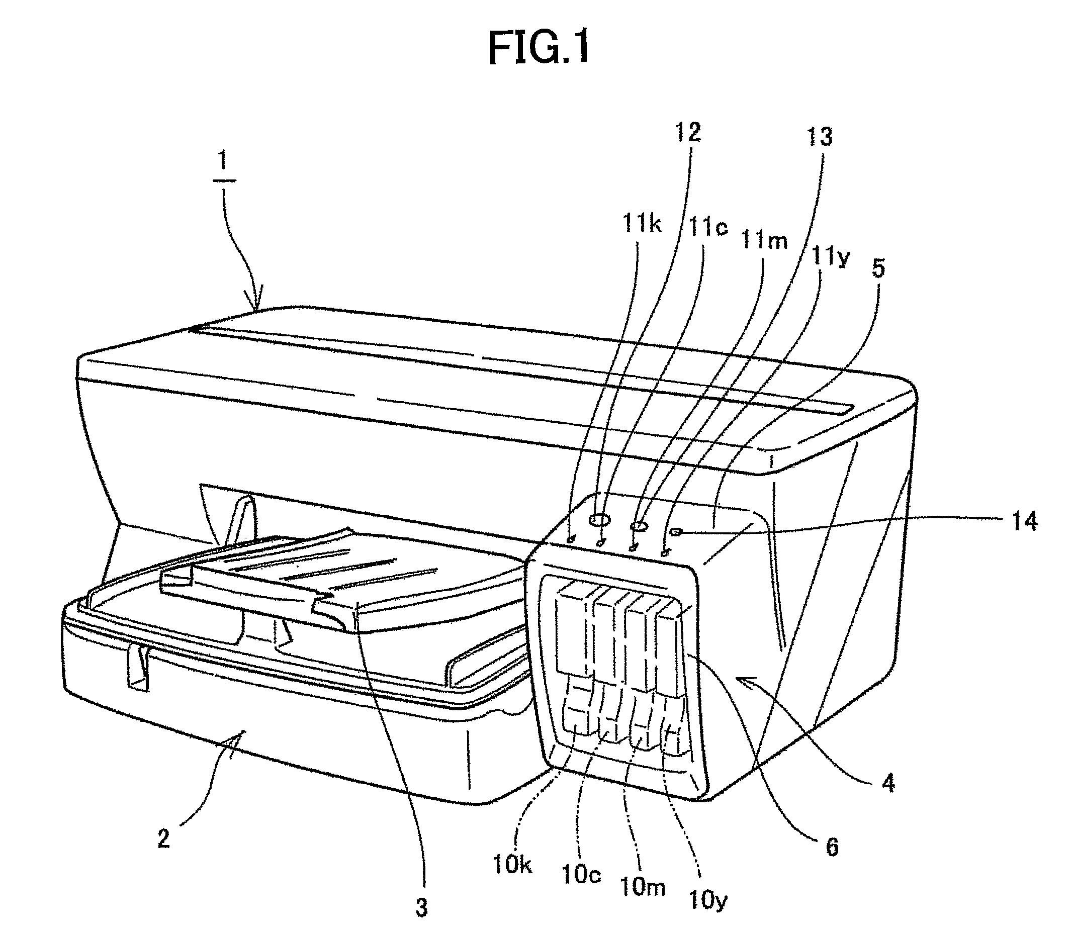
[0030]A description of examples and exemplary embodiments according to the present invention will be provided below with reference to FIGS. 1 through 14. FIG. 1 is a perspective view of an image forming apparatus, according to an exemplary embodiment of the present disclosure, viewed from a front of the apparatus.

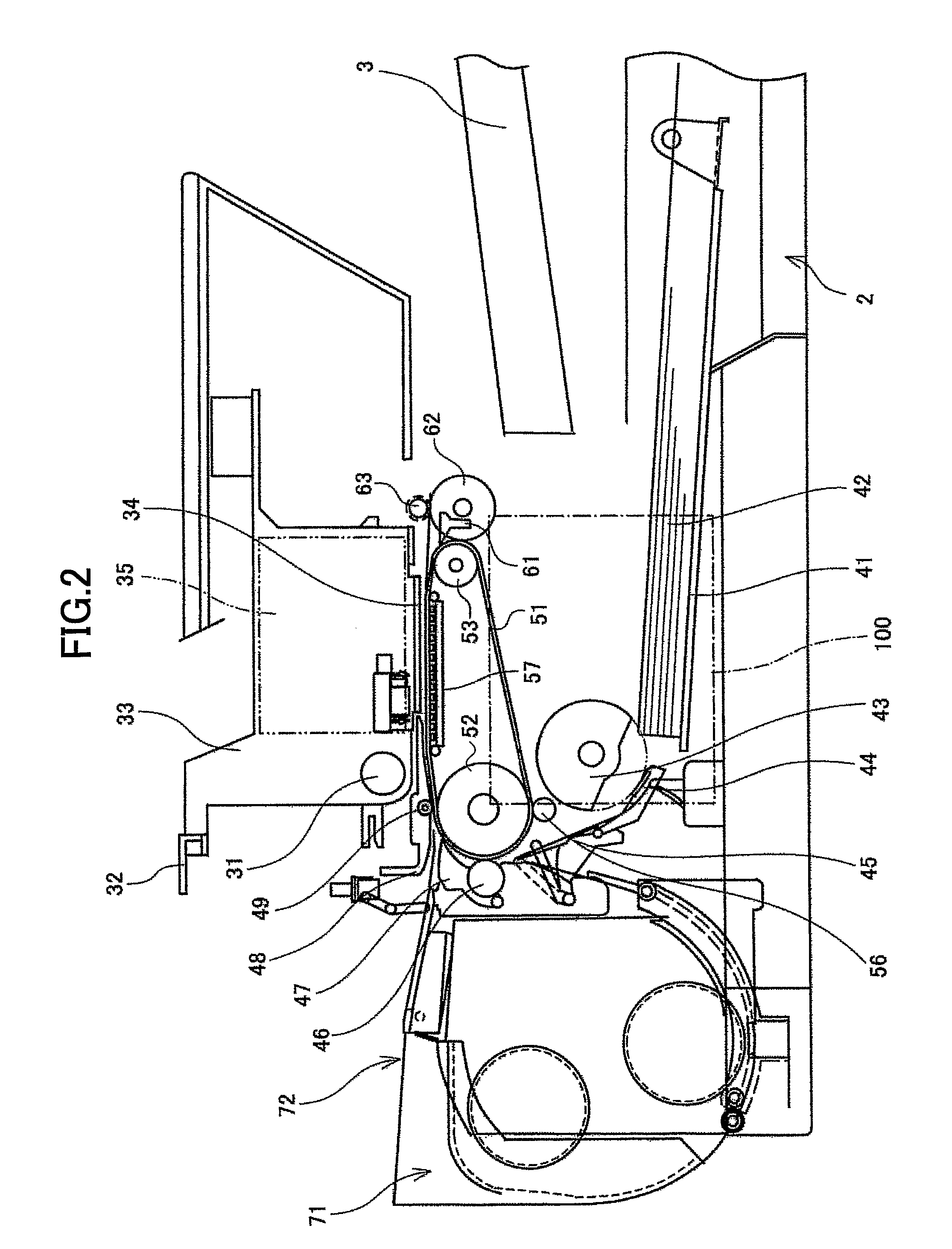
[0031]The image forming apparatus includes a main apparatus body 1, a paper supply tray 2 for supplying recording media such as paper that are loaded into the main apparatus body 1, and a paper eject tray 3 on which the recording media such as paper that are recorded (formed) with images are stacked. The paper eject tray 3 is detachably provided on the main apparatus body 1. A cartridge loading part 4 is provided on one end on the front face of the main apparatus body 1, that is, on one side of the paper eject tray 3. The cartridge loading part 4 projects frontward from the front face of the main apparatus body 1, and has a top surface lower than the top surface of the main...


PUM


Abstract

An image forming apparatus for forming an image on a recording medium by ejecting drops of recording fluid from a recording head includes a waste tank having a space for containing waste fluid, a part for obtaining a correlation value that has a correlation to a deposited state of the waste fluid in the space within the waste tank, and a part for judging whether or not the correlation value exceeds a reference value.

Description

TECHNICAL FIELD[0001]The present invention generally relates to image forming apparatuses, and more particularly to an image forming apparatus that is provided with a waste tank or container for containing waste ink.BACKGROUND ART[0002]As image forming apparatuses such as printers, facsimile apparatuses, copying apparatuses and composite (or multi-function) apparatuses having the functions of the printer, facsimile apparatus and copying apparatus, there are the so-called ink-jet recording apparatuses which use an ink-jet recording head, for example. The ink-jet recording apparatus makes an image formation on a recording medium by ejecting ink from the ink-jet recording head onto the recording medium. The recording medium may be paper, OHP film or any suitable recording sheet onto which the ink may be adhered. The image formation includes various kinds of recording and printing of characters, images and / or photographs. In the ink-jet recording apparatus, it is essential to provide a ...

Claims


Application Information

Patent Timeline
Patent Type & Authority Patents(United States)
IPC IPC(8): B41J2/165
CPCB41J2/16523B41J29/38B41J2/185B41J2/17509B41J29/02
Inventor TAMAI, TOMOHIROKANEKO, TETSUYA
Owner RICOH KK
Learn More