Power generator

a portable power generator and power supply technology, applied in the direction of electrochemical generators, emergency power supply arrangements, electric generator control, etc., can solve the problems of not revealing the addition of fuel, waste of resources and increase costs, and rapid exhaustion of the secondary battery used in the compact portable devi

Inactive Publication Date: 2008-07-29
HITACHI LTD
View PDF10 Cites 6 Cited by
  • Summary
  • Abstract
  • Description
  • Claims
  • Application Information

AI Technical Summary

Benefits of technology

[0010]Thus, an object of the present invention is to provide a portable power generator that can ensure the capacity for fuel and can easily add the fuel.

Problems solved by technology

This causes a battery (a secondary battery) used in the compact portable devices to be rapidly exhausted, and the battery needs to be charged at home and also away from home or in transit.
To charge a secondary battery away from home or in transit, portable power supplies that can be quickly charged using a dry cell are commercially available, but the dry cell is disposable to cause a waste of resources and increase costs.
A portable power supply using a solar panel has been also proposed, but tends to be affected by the weather.
Also, the examples do not disclose addition of fuel that is important in usability.
A treatment method of moisture produced during power generation is a problem specific to fuel cells.
In the conventional fuel cell, however, a vent for releasing moisture as vapor is insufficiently formed to prevent an increase in exhaust efficiency.
A sufficiently formed vent increases the exhaust efficiency, but also increases the size of the fuel cell itself, which causes the power generator to be less portable.

Method used


Image

  • Power generator
  • Power generator
  • Power generator

Examples


embodiment 1

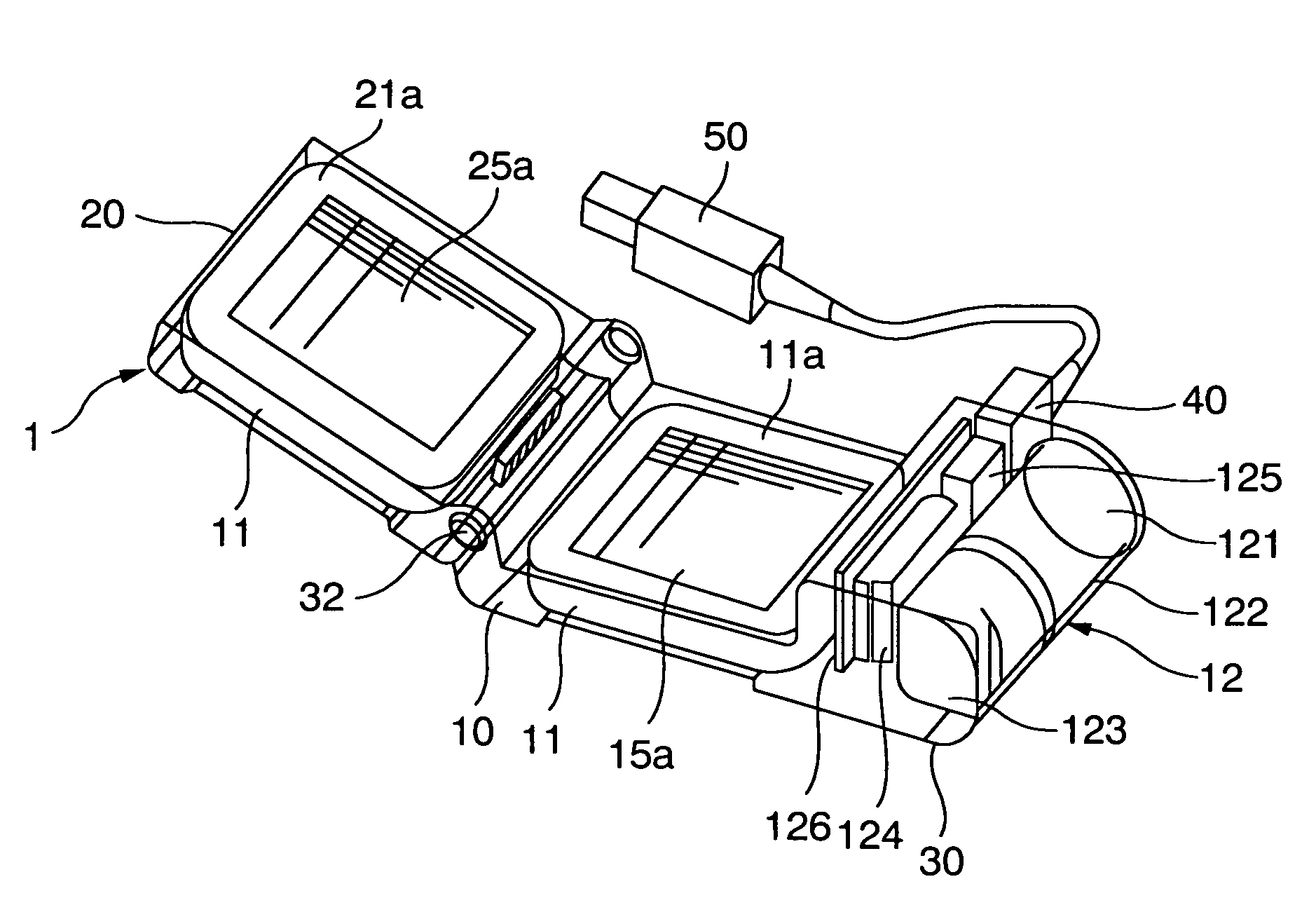
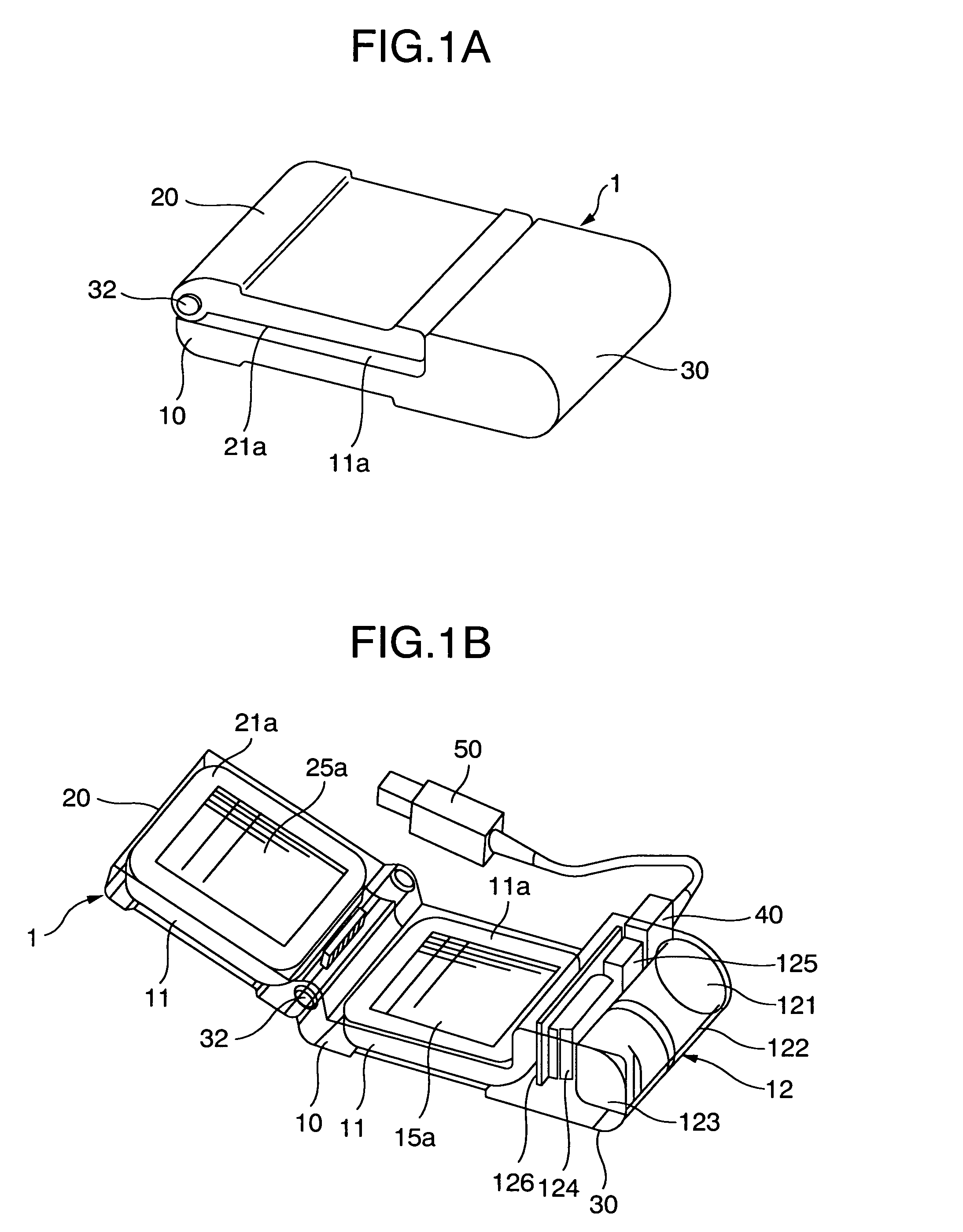
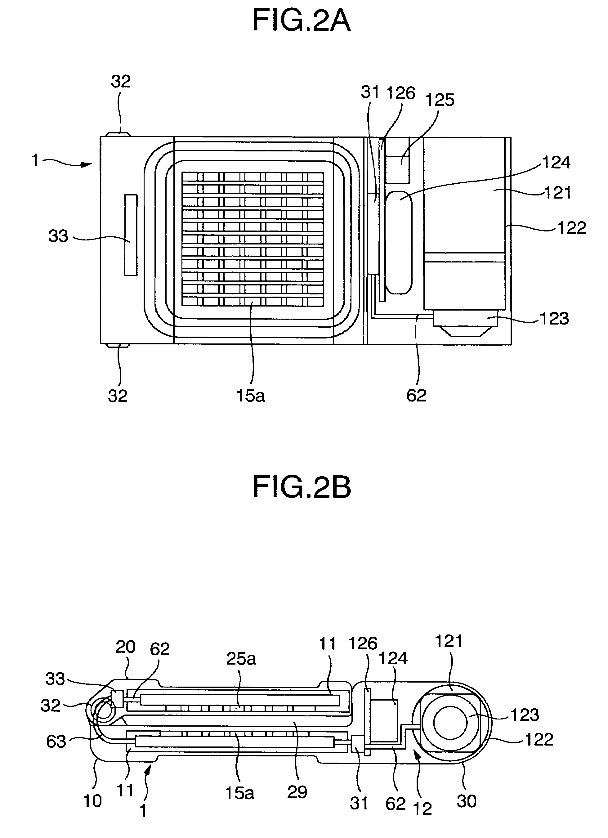
[0079]FIGS. 1 to 4 show a portable power generator according to a first embodiment of the present invention. First, a schematic structure of the power generator according to the first embodiment will be described with reference to FIGS. 1 to 3.

[0080]FIG. 1 shows a schematic structure of the power generator according to the first embodiment, FIG. 1A is a perspective view of an appearance, and FIG. 1B is a schematic perspective view of an internal layout. FIG. 2 shows an internal layout of the power generator according to the first embodiment in a closed state, FIG. 2A is a front view, and FIG. 2B is a bottom plan view. FIG. 3 shows an internal layout of the power generator according to the first embodiment in an opened state, FIG. 3A is a front view, and FIG. 3B is a bottom plan view.

[0081]In FIGS. 1 to 3, the power generator 1 according to the embodiment includes a first power generation casing 10 and a second power generation casing 20 having power generation elements 11 therein, a...

embodiment 2

[0102]Next, a portable power generator according to a second embodiment of the present invention will be described with reference to FIGS. 5 and 6. FIG. 5 shows a schematic structure of the power generator according to the second embodiment, FIG. 5A is a perspective view of an appearance, and FIG. 5B is a perspective rear view. FIG. 6 shows an exhaust structure of the power generator according to the second embodiment, FIG. 6A shows an exhaust structure in an opened state, and FIG. 6B shows an exhaust structure in a closed state.

[0103]The power generator according to the second embodiment has a feature in that vents are formed in inner surfaces and outer surfaces of two power generation casings.

[0104]In FIGS. 5 and 6, the power generator 2 according to the embodiment includes a first power generation casing 10 and a second power generation casing 20 having power generation elements 11 therein, a main casing 30 having a fuel supply portion 12 therein, and a connecting portion that co...

embodiment 3

[0110]Next, a portable power generator according to a third embodiment of the present invention will be described with reference to FIGS. 7 to 10. FIG. 7 shows an appearance of the power generator according to the third embodiment, FIG. 7A is a top view, FIG. 7B is a front view, and FIG. 7C is a right side view. FIG. 8 shows the state of use of the power generator according to the third embodiment. FIG. 9 schematically shows the state of use of the power generator according to the third embodiment, FIG. 9A is a side view of a state with a small opening angle, and FIG. 9B is a side view of a state with a large opening angle. FIG. 10 shows an modified example of the power generator according to the third embodiment.

[0111]The power generator according to the third embodiment has a feature in that a fuel supply portion (a main casing) has a connecting mechanism, and a first power generation casing and a second power generation casing are openably and closably connected using the fuel su...


PUM


Abstract

There is provided a power generator including a plurality of power generation elements, and a fuel supply portion that communicates with the plurality of power generation elements through a fuel supply passage, the plurality of power generation elements are housed in a plurality of independent power generation casings having vent portions, and the plurality of power generation casings are movably connected via a connecting portion so as to enter a housing state where the casings are placed on top of each other and a power generation state where the casings are separated. There is provided a portable power generator that can ensure sufficient ventilation and power generation areas in use (during power generation), and becomes compact when carried.

Description

INCORPORATION BY REFERENCE[0001]The present application claims priority from Japanese application JP2006-096409 filed on Mar. 31, 2006, the content of which is hereby incorporated by reference into this application.BACKGROUND OF THE INVENTION[0002](1) Field of the Invention[0003]The present invention relates to a portable power generator for charging a compact portable device including a chargeable power supply such as a mobile phone, a personal digital assistant, a shaver, or a portable audio device.[0004](2) Description of Related Art[0005]In recent years, compact portable devices such as mobile phones or personal digital assistants have become more sophisticated and required a larger amount of electric power. This causes a battery (a secondary battery) used in the compact portable devices to be rapidly exhausted, and the battery needs to be charged at home and also away from home or in transit.[0006]To charge a secondary battery away from home or in transit, portable power suppli...

Claims


Application Information

Patent Timeline
Patent Type & Authority Patents(United States)
IPC IPC(8): H02P9/04
CPCH01M8/04119H01M8/04208H01M8/2475H01M8/249Y02B90/18H01M2250/30Y02E60/523Y02E60/50H01M2008/1095Y02B90/10
Inventor SUSO, KOJI
Owner HITACHI LTD
Why Eureka
Try Eureka