
Remote control of lighting

a remote control and lighting technology, applied in the field of remote control of lighting, can solve the problems of increasing cost, increasing the number of limitations of this common means of on/off control, and increasing the complexity of the power switching arrangemen

Inactive Publication Date: 2008-07-29
WILHELM WILLIAM GEORGE +1
View PDF5 Cites 13 Cited by
  • Summary
  • Abstract
  • Description
  • Claims
  • Application Information

AI Technical Summary

Benefits of technology

"The present invention is a system for controlling the on / off of electronic ballasts or other devices with low power consumption. The system uses a low-power controller that is isolated from the primary power circuit, reducing power loss and allowing for efficient control. The controller operates with a low amount of control current and little power loss. The system includes a remote switch function that can be located anywhere in the world, providing high electrical isolation between the switch and the power electronics of the ballast. The system can be used for proportional light dimming control, providing a linear response. The system can be used for non-ballased lighting fixtures and other devices that require on / off control."

Problems solved by technology

Because of the special knowledge associated with such power wiring a costly professional electrician is formally required to alter any switching control within a given building space.
There are a number of limitations associated with this common means for on / off control.
When this happens the power switching arrangement becomes complex with power switching implemented through a combination of mechanical and electric relays (contactors) that increase to hardware needs, increase expense and reduced reliability of the system.
Another limitation occurs if the switch is very remote and distant for the lights, requiring the lighting load current to pass to and from the remote switch causing an undesirable electrical loss corresponding to resistive voltage drops.
Additionally, such a system is inflexible to alterations and modifications, essentially requiring the special training and experience of higher cost electric contract service assistance, to alter a switching arrangement, or to add automated remote functions to the lights.

Method used


Image

  • Remote control of lighting
  • Remote control of lighting
  • Remote control of lighting

Examples


Embodiment Construction

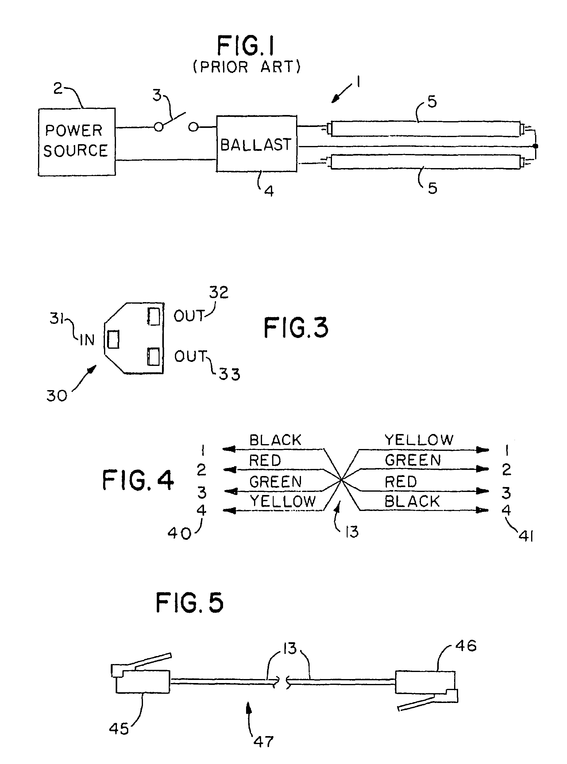
[0041]A block diagram of a prior art lighting circuit 1 is shown in Figure I. A power source 2 is used to power ballast 4 which operates two gas discharge (fluorescent) lamps 5. On / off control of the lamps is influenced by mechanical switch 3 which must be rated for the full supply voltage and current requirements of the lamp load, when multiple ballasts are used in parallel. A long distance from switch 3 to ballast 4 requires evaluation of the effects of the consequent voltage drop. In most jurisdictions, the initial switch wiring as well as any alterations is legally performed only by a licensed electrician.

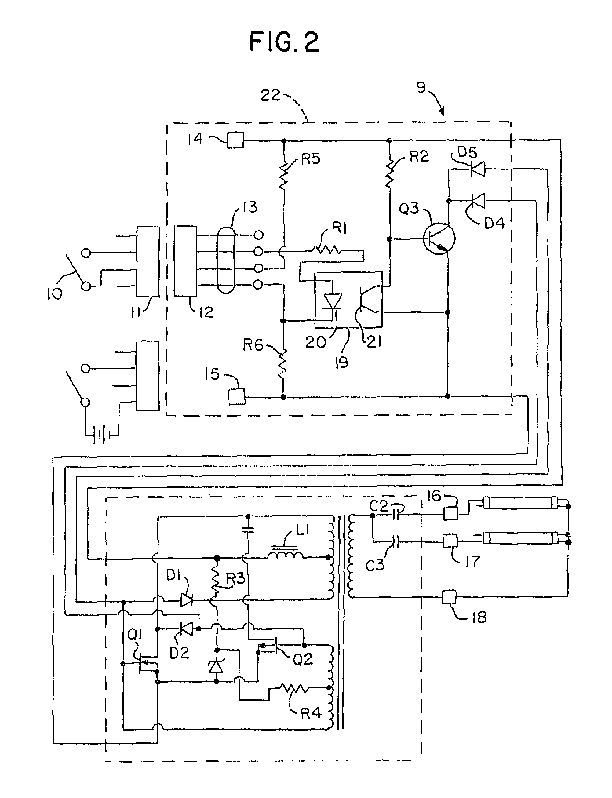
[0042]FIG. 2 is a schematic diagram of an electronic ballast 9 of this invention. A control switch 10 is wired to connector 11. A cable (not shown) connects connector 11 to connector 12; this could be a long distance. A length of flat 4-conductor telephone or any corresponding signal type cable 13 goes from connector 12 to connections within ballast 9. Terminals 14 and 15 suppl...


PUM


Abstract

An electronic ballast system controls one or more ballasts of HID or fluorescent lamps, which are controlled in an “on / off” manner by a ultra low power controller that is isolated for a primary power circuit or derives its very low switch power from the ballast itself. The on / off control provides a near lossless control system. This system may be applied to electronic ballast for operates at fractional power levels corresponding to different lighting intensities and with conventional occupancy sensors. The system may also be applied to other electronically compatible end-use devices and applications.

Description

RELATED APPLICATIONS[0001]This application is based in part upon provisional patent application Ser. No. 60 / 293,707, filed May 21, 2001, and upon application Ser. No. 10 / 779,291, filed Feb. 13, 2004, which was a continuation of application Ser. No. 10 / 153,522, filed May 22, 2002, now U.S. Pat. No. 6,693,395.FIELD OF THE INVENTION[0002]The present invention relates to a system and device for low power consumption of on / off control of a single or a plurality of electronic ballasts that can be used for a variety of lighting functions.BACKGROUND[0003]Electronic ballasting of gas discharge lighting has become the leading option over passive reactive ballasting. Gas discharging lighting includes fluorescent and high intensity discharge (HID) lamps. Electronic ballasts are constructed with active electronic components such as transistors that allow functional electrical control. The normal operation of the ballasted lights requires them to be energized or de-energized corresponding to “on ...

Claims


Application Information

Patent Timeline
Patent Type & Authority Patents(United States)
IPC IPC(8): G05F1/00F21Y101/00H05B44/00
CPCH05B33/0809H05B33/0815H05B33/0845H05B39/086H05B41/3921H05B37/0245Y02B20/346H05B45/10H05B47/175Y02B20/30H05B45/375
Inventor WILHELM, WILLIAM GEORGESAVAGE, PAUL
Owner WILHELM WILLIAM GEORGE
Learn More