Method and system for detecting with laser the passage by a vehicle of a point for monitoring on a road

a technology of laser detection and monitoring point, which is applied in the direction of traffic control system, hydraulic/pneumatic signalling details, reradiation, etc., can solve the problems of increasing less acceptable, requiring modifications to the road surface, and limited number of sensors which can be accommodated at a given location in the road surface. , to achieve the effect of simplifying the placement and saving equipment costs

Active Publication Date: 2008-07-29
GATSOMETER
View PDF10 Cites 40 Cited by
  • Summary
  • Abstract
  • Description
  • Claims
  • Application Information

AI Technical Summary

Benefits of technology

[0008]In order to prevent incorrect detections as a result of for instance noise or birds passing through the laser beam, a profile of the vehicle is preferably determined each time from a number of successively received reflections of a laser beam, and a detection of the vehicle passing the point for monitoring is only valid if the profiles determined from reflections of the various laser beams correspond precisely. In this way also non-watertight detections, for instance in case the vehicle changes lanes when passing the point for monitoring, will be filtered out automatically, thus preventing problems of proof.
[0011]So as to ensure that each detection results in useful and comparable reflections, the distance between the transmitting and receiving location and the point for monitoring on the one hand and the characteristic of the at least one transmitted laser beam on the other are preferably matched such that each laser beam hits the passing vehicles at a characteristic height. For each vehicle reflections of e.g. the bonnet, the windscreen pillar, the dors and the boot may be received, so as to create a well analysable profile.
[0012]When the road comprises a number of lanes, on each of which a specific point is to be monitored, it is recommended that for each lane a laser beam is transmitted at a related angle from the transmitting and receiving location. A plurality of lanes can thus be monitored from a single transmitting and receiving location, which results in savings in the cost of equipment and simplification of placing.

Problems solved by technology

The drawback which all said methods have in common is that they require modifications to the road surface at the location to be monitored, for instance a stop line at a traffic light.
This is increasingly less acceptable as the amount of traffic increases, all the more so because it is usually precisely at the busiest points in the road network that the detectors are required.
Furthermore, the number of sensors which can be accommodated at a given location in the road surface is limited, since there must be sufficient space between them so that they do not affect each other's operation.

Method used


Image

  • Method and system for detecting with laser the passage by a vehicle of a point for monitoring on a road
  • Method and system for detecting with laser the passage by a vehicle of a point for monitoring on a road
  • Method and system for detecting with laser the passage by a vehicle of a point for monitoring on a road

Examples


Embodiment Construction

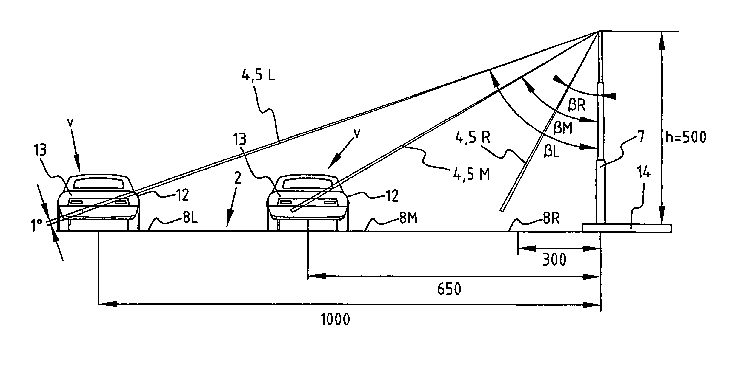
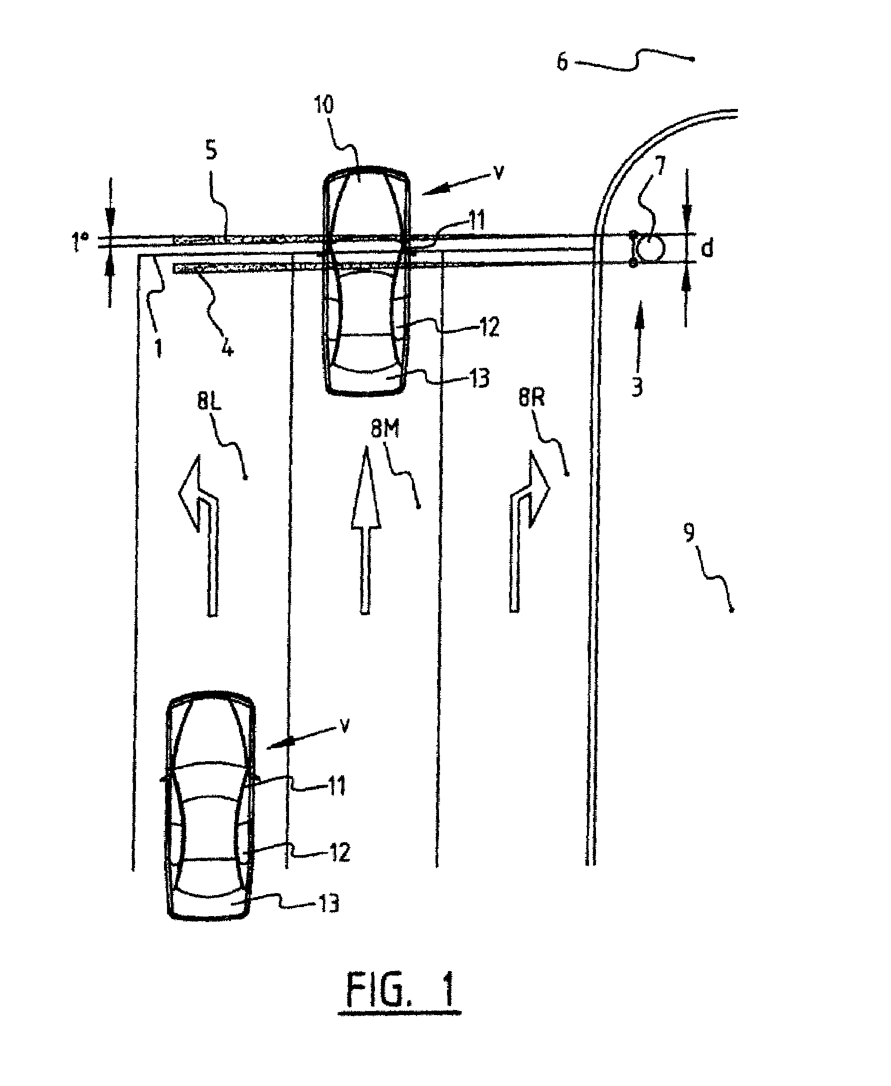
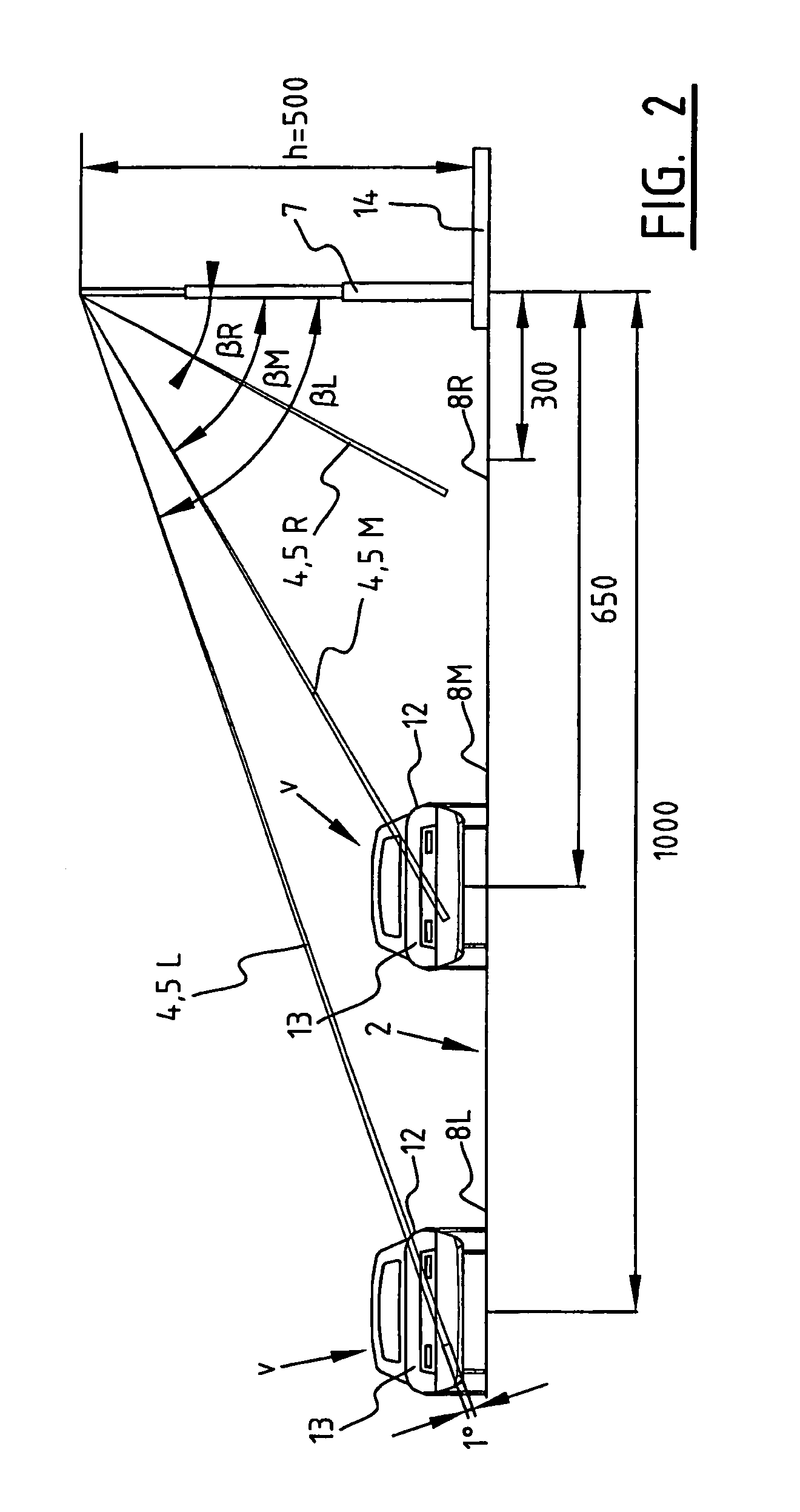
[0018]The invention relates to a system for detecting passing of a determined point for monitoring 1 on a road 2, in this case a stop line at an intersection of the road and another road 6, which intersection is protected with traffic lights (not shown here) (FIG. 1). This detection system comprises a device 3 for transmitting a pair of parallel laser beams 4, 5 to the point for monitoring 1, and receiving reflections of the laser beams 4, 5 generated by passing vehicles V. The transmitting and receiving device 3, which is disposed at a location remote from stop line 1, here on the pavement 9 in line with the stop line 1, is further adapted to determine from the received reflections that a vehicle V is passing stop line 1.

[0019]In the shown embodiment the road 2 on which the stop line 1 is drawn has a lane 8L for traffic turning left, a middle lane 8M for traffic going straight on, and a lane 8R for traffic turning right. The transmitting and receiving device or laser device 3 is th...


PUM


Abstract

The invention relates to a method for detecting the passage by a vehicle of a determined point for monitoring on a road, wherein from a remotely situated location a laser beam is transmitted continuously to the point for monitoring, reflections from the transmitted laser beam are received at the remotely situated location, and it is determined from the received reflections that the vehicle is passing the point for monitoring. The laser beam can be transmitted at right angles to the travel direction of the passing vehicle. The detection can be used to activate a red-light camera, to measure the speed of the vehicle or measure the traffic intensity, without sensors, for instance induction loops, having to be arranged in the road for this purpose. The invention further relates to a system for performing this method.

Description

CROSS REFERENCE TO RELATED APPLICATIONS[0001]This application claims priority to Dutch Application Number 1027020, filed Sep. 10, 2004.TECHNICAL FIELD[0002]The invention relates to a method for detecting the passage by a vehicle of a determined point for monitoring on a road. Such a method is generally known, and is used for instance in establishing traffic violations such as driving through a red light, or in measurements of traffic density, for instance for the purpose of guiding traffic in order to enhance traffic flow.BACKGROUND OF THE INVENTION[0003]In most known methods use is made of sensors which are mounted in or on the road surface. A classic example are air-filled conduits laid over the road surface which record a pressure difference when the wheels of a vehicle drive over them. Loads on the road surface by passing vehicles can also be detected using piezoelectric elements embedded in the road surface. Most widely used however are inductive detections. Here the change is ...

Claims


Application Information

Patent Timeline
Patent Type & Authority Patents(United States)
IPC IPC(8): G08B1/04
CPCG08G1/01G01S17/88
Inventor JANSSEN, THEODORUS MARIA
Owner GATSOMETER
Why Eureka
Try Eureka