

Image forming method and apparatus
a technology of image forming and forming method, which is applied in the direction of electrical equipment, instruments, printing, etc., can solve the problems of inconstant scanning pitch in the sub scanning direction, image defect, etc., and achieve the effect of preventing image defect, reducing the density difference between the halftone image formed in the left-end area and the right-end area, and reducing the number of forming steps
- Summary
- Abstract
- Description
- Claims
- Application Information
AI Technical Summary
Benefits of technology
Problems solved by technology
Method used
Image

Examples
first embodiment
Modifications of First Embodiment
[0097]It is noted that the invention is not limited to the first embodiment described above but various modifications may be made thereto so long as such modifications do not deviate from the scope of the invention. In the cell arrangement of the embodiment, the particular contiguous location PCL is provided at each of the contiguous locations in the main scanning direction X. However, the mode of provision of the particular contiguous location PCL is not limited to this. For example, the particular contiguous locations may be periodically disposed similarly to the above embodiment or may be disposed in a non-periodic manner. As other modes of periodically disposing the particular contiguous locations PCL, the particular contiguous location PCL may be provided at every two contiguous locations in the main scanning direction X, as shown in FIG. 13 for example. It is noted here that FIG. 13 is a diagram showing another embodiment of the invention. In F...
second embodiment
Halftoning Process
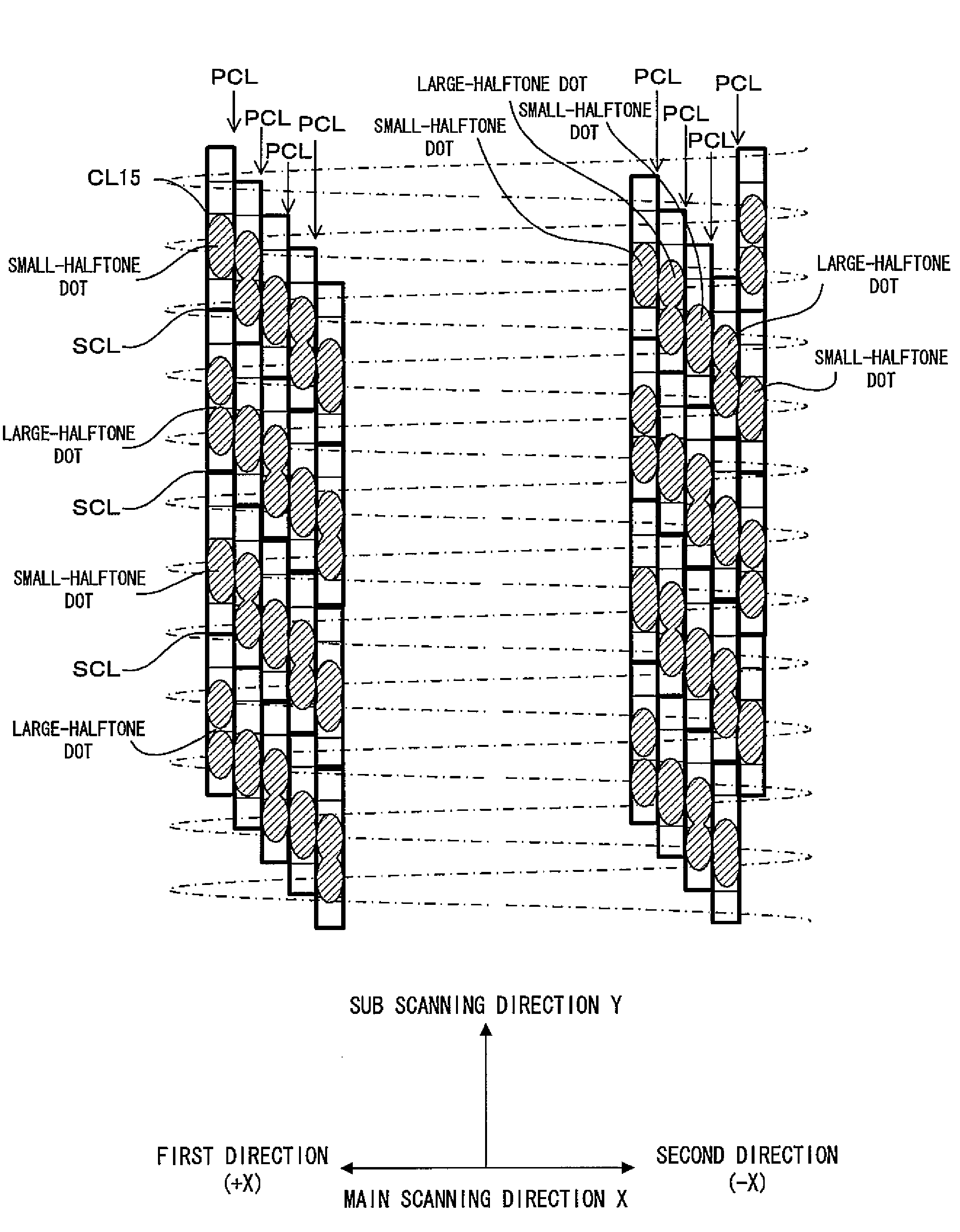
[0100]According to a second embodiment, the halftoning processor 1152, similarly to that of the first embodiment, generates the halftone data by applying the fattening type threshold matrix MTX to the corrected tone data outputted from the tone corrector 1151. The halftoning process according to the second embodiment will be described as below with reference to FIG. 15, FIG. 16A and FIG. 16B. FIG. 15 is a diagram showing the halftoning process performed by the halftoning processor 1152. The second embodiment uses a 1×5 cell CL15 consisting of one pixel in the main scanning direction X and five pixels in the sub scanning direction Y. Some of the pixels of the 1×5 cell CL15 that correspond to a tone level are exclusively subjected to light exposure and development for formation of pixel-dots. In this process, which of the pixels is subjected to the formation of a pixel-dot is decided based on the result of comparison between the corrected tone data and the threshold ...
third embodiment
[0106]Next, description is made on an image forming method and image forming apparatus according to a third embodiment of the invention. It is noted that the embodiment is constituted the same way as the second embodiment except for the cell arrangement. Hence, only the cell arrangement as a feature of the third embodiment is described here, while the description of the other features is dispensed with. FIG. 18 is a diagram showing the image forming method and image forming apparatus according to the third embodiment of the invention. In FIG. 18, a dot-dash line represents the scanning line as the track on which the light beam is scanned; a rectangle in bold solid line represents the 1×5 cell CL15; and an ellipse in solid line (cross-hatched area) represents the area where the pixel-dot is formed by irradiating the beam spot and developing the irradiated area. In the third embodiment as shown in FIG. 18, the 1×5 cells CL15 are arranged in the sub scanning direction Y similarly to th...
PUM
 Abstract
Description
Claims
Application Information