Apparatus and method for detecting blockage of impulse lines

a technology of impulse line and apparatus, applied in the direction of fluid pressure measurement, liquid/fluent solid measurement, machine/engine, etc., can solve the problem of difficult to set a threshold that is compared to the ratio (d=ssph/sspl), the ratio is non-infinite, and the transmitter generates a noise-containing output signal. problem, to achieve the effect of convenient setting a threshold

Active Publication Date: 2008-07-29
HASHIZUME TAKUMI +3
View PDF6 Cites 9 Cited by
  • Summary
  • Abstract
  • Description
  • Claims
  • Application Information

AI Technical Summary

Benefits of technology

[0028]It is another object of the present invention to provide an apparatus for detecting a blockage of an impulse line or impulse lines, wherein the apparatus is free from the disadvantages described above.
[0029]It is a further object of the present invention to provide an apparatus configured to allow a user to conformably and conveniently set a threshold to be used in detecting a blockage of an impulse line or impulse lines.
[0032]It is an additional object of the present invention to provide a method of allowing a user to conformably and conveniently set a threshold to be used in detecting a blockage of an impulse line or impulse lines.

Problems solved by technology

Actually, however, the differential pressure transmitter generates a noise-containing output signal.
Actually, however, the output signal noise may cause the ratio (D=Ssph / Sspl) to be a non-infinite value, for example, approximately 20.
The second conventional technique makes it difficult to set a threshold that is compared to the ratio (D=Ssph / Sspl).
This makes it inconvenient and difficult for a user to set the threshold.

Method used


Image

  • Apparatus and method for detecting blockage of impulse lines
  • Apparatus and method for detecting blockage of impulse lines
  • Apparatus and method for detecting blockage of impulse lines

Examples


Embodiment Construction

[0042]Selected embodiments of the present invention will now be described with reference to the drawings. It will be apparent to those skilled in the art from this disclosure that the following descriptions of the embodiments of the present invention are provided for illustration only and not for the purpose of limiting the invention as defined by the appended claims and their equivalents.

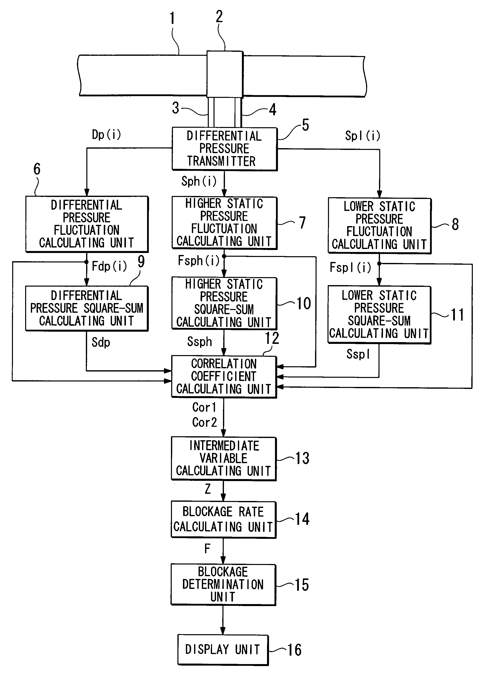
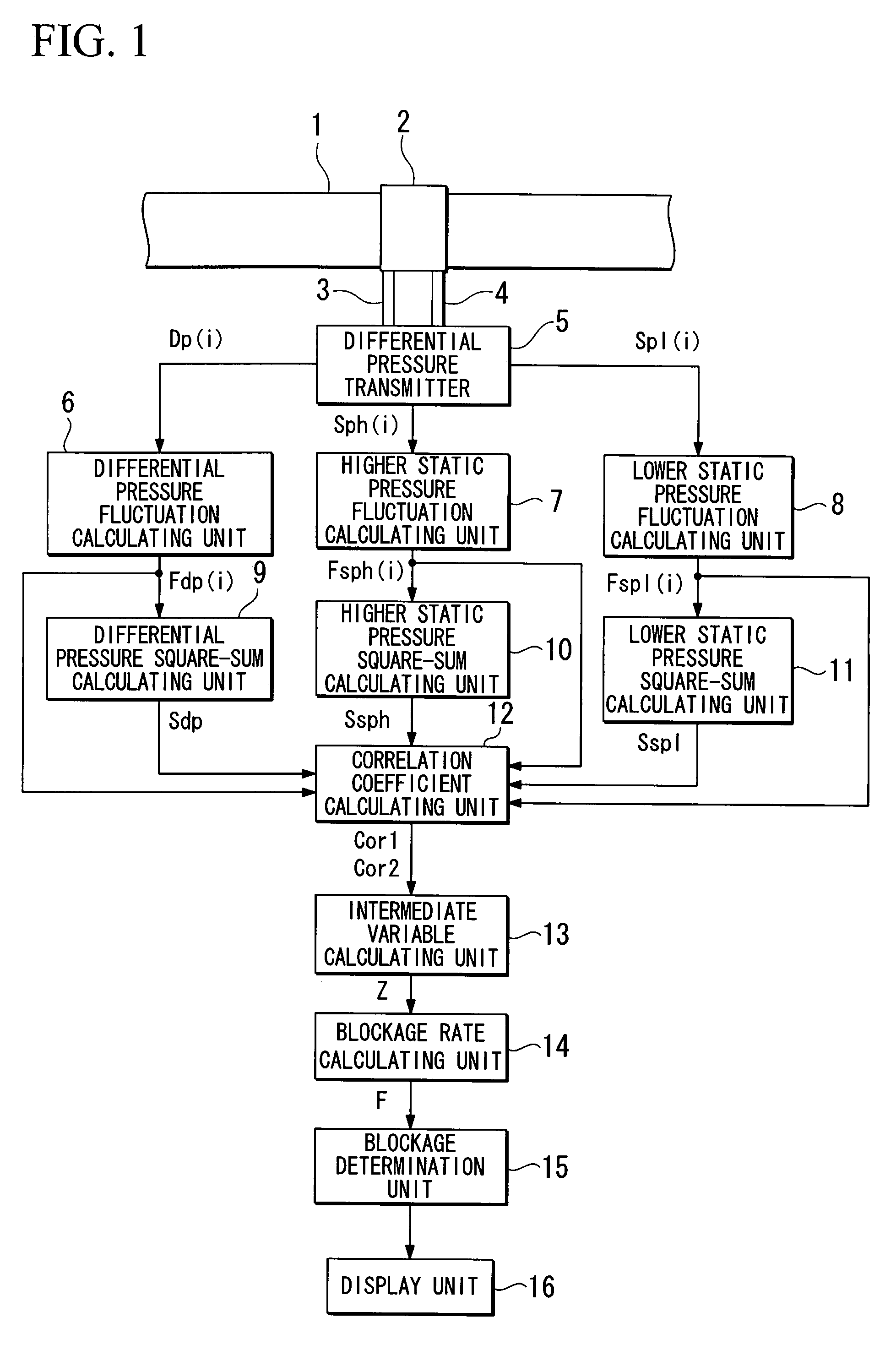
[0043]FIG. 1 is a schematic view illustrating an apparatus for detecting a blockage of impulse lines in accordance with a first embodiment of the present invention. The detecting apparatus is configured to detect a blockage of higher and lower pressure impulse lines 3 and 4. The higher and lower pressure impulse lines 3 and 4 are coupled to a tube 1 upstream and downstream of an orifice 2, respectively, wherein the tube 1 is configured to allow a fluid to flow in a direction from the lift side to the right side through the orifice 2 of the drawing of FIG. 1. The higher and lower pressure impulse li...


PUM

PropertyMeasurementUnit
differential pressureaaaaaaaaaa
pressureaaaaaaaaaa
static pressureaaaaaaaaaa

Abstract

A detecting apparatus includes the following units. A pressure detecting unit detects in time series higher and lower static pressures and a differential pressure. Fluctuation calculating units calculate time series data sets of a differential pressure fluctuation, a higher static pressure fluctuation, and a lower static pressure fluctuation. Square sum calculating units calculate the square sum of the time series data sets of the differential pressure fluctuation, the square sum of the time series data sets of the higher static pressure fluctuation, and the square sum of the time series data sets of the lower static pressure fluctuation. A correlation coefficient calculating unit calculates first and second correlation coefficients. An intermediate variable calculating unit calculates an intermediate variable. A blockage rate calculating unit calculates a blockage rate. A determination unit determines a blockage of higher and lower pressure impulse lines with reference to the blockage rate.

Description

BACKGROUND OF THE INVENTION[0001]1. Field of the Invention[0002]The present invention generally relates to an apparatus and method for detecting blockage of impulse lines. More specifically, the present invention relates to an apparatus and method for detecting blockage of impulse lines that are coupled to a differential pressure transmitter, wherein the differential pressure transmitter is configured to measure the differential pressure of a fluid that flows through a tube.[0003]Priority is claimed on Japanese Patent Application No. 2006-84524, filed Mar. 27, 2006, the content of which is incorporated herein by reference.[0004]2. Description of the Related Art[0005]All patents, patent applications, patent publications, scientific articles, and the like, which will hereinafter be cited or identified in the present application, will hereby be incorporated by reference in their entirety in order to describe more fully the state of the art to which the present invention pertains.[0006]...

Claims


Application Information

Patent Timeline
Patent Type & Authority Patents(United States)
IPC IPC(8): G01F1/34G06F15/00G01L13/00
CPCG01L27/007
Inventor HASHIZUME, TAKUMIWAKUI, TETSUYAEINO, JYUN-ICHIMIYAJI, NOBUO
Owner HASHIZUME TAKUMI
Why Eureka
Try Eureka