Method and apparatus to create a waveform for driving a printhead

a printing head and waveform technology, applied in printing, inking apparatus, other printing apparatus, etc., can solve the problems of high consistency requirements for printhead manufacturing, inconsistent or uncontrollable jetting, and three parameters per pulse to create a waveform, so as to achieve fast and more accurate printing methods, limit the applicability, and improve the effect of printing speed

Active Publication Date: 2008-08-05
XAAR TECH LTD
View PDF5 Cites 12 Cited by
  • Summary
  • Abstract
  • Description
  • Claims
  • Application Information

AI Technical Summary

Benefits of technology

[0019]Although controlling the size and velocity of small ink drops or droplets merging together into one big ink drop is known from the prior art, most of the prior art methods have limited applicability at high printing rates or require a very elaborate control mechanism for waveform parameters. As present-day greyscale printers still require faster and more accurate printing methods, it would be advantageous to have the velocity of the small droplets as high as possible so they merge either on the nozzle plate or in flight before striking the printing substrate have all drop volumes flying at the same velocity to reduce dot misplacement errors, and have the number of waveform tuning parameters limited.SUMMARY OF THE INVENTION

Problems solved by technology

A disadvantage of the method is that, for creating different droplets, always the same waveform is to be used.
Further, the resonant frequency can be sensitive to small changes in the mechanical properties of the printhead, imposing high consistency requirements on printhead manufacturing.
By using the same waveforms to generate first and subsequent droplets, there will be an excess of energy present in the ink chamber, possibly leading to inconsistent or uncontrollable jetting.
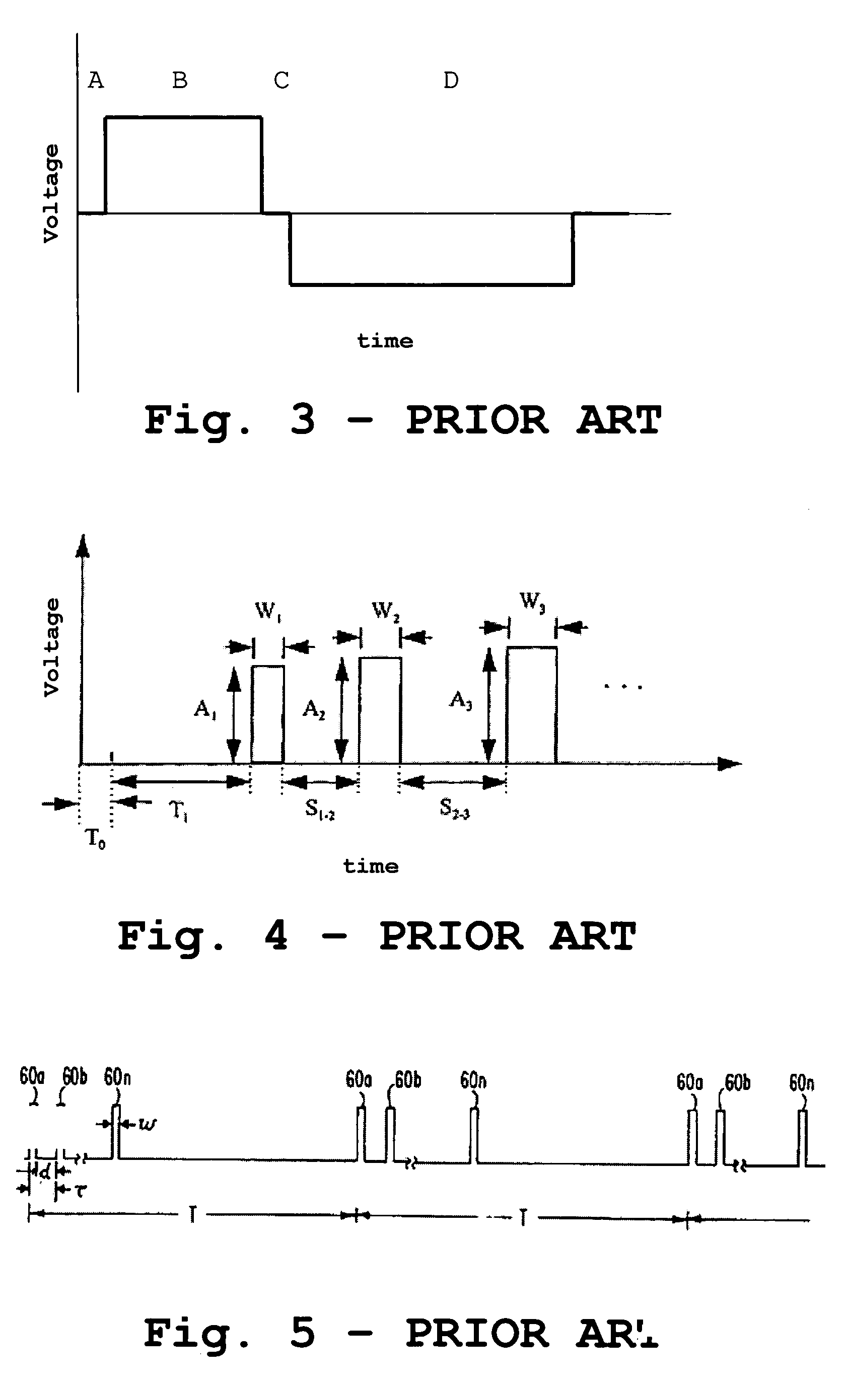
Although the method described in U.S. Pat. No. 6,102,513 deals with a number of the problems linked with the method described in U.S. Pat. No. 5,202,659, a disadvantage of the method is that three parameters per pulse have to be determined to create a waveform, i.e. pulse width, pulse delay and pulse amplitude.
A disadvantage of the method described in this document is that again, 3 parameters need to be taken into account, i.e. amplitude of each pulse, the length of each pulse and the time between every two pulses.
Therefore, it is not possible to print at very high rates, using the method described in U.S. Pat. No. 5,285,215.
Hence, the method described in U.S. Pat. No. 4,513,299 does not allow printing of ink drops, including a different number of droplets or subvolumes of ink, with all drops having the same velocity.

Method used


Image

  • Method and apparatus to create a waveform for driving a printhead
  • Method and apparatus to create a waveform for driving a printhead
  • Method and apparatus to create a waveform for driving a printhead

Examples


first embodiment

[0069]In the invention a waveform is created for printing at 1 dpd that provides high drop generation frequency resulting in high printing speeds, and stable drop generation resulting in for example reproducible drop volumes and drop velocities. A 1 dpd printing system may also be called a binary printing system. FIG. 8 shows an example of a waveform that is able to create one droplet. The waveform includes one pulse 80 that may have a width L1 and that may be represented with a number of bits depending the width L1 and the sample clock period used.

[0070]The pulse 80 includes an opening pulse 81, creating outward bending of channel walls of a chamber so as to engage the pull phase of the chamber, and a closing pulse 82, leading to drop generation and ejection.

[0071]In a specific example, the sample clock may be chosen at for example 100 ns. A waveform 80 as shown in FIG. 8 with for example L1=1000 ns and a sample clock of 100 ns may be created by use of the following signal:

[0072]

On...

second embodiment

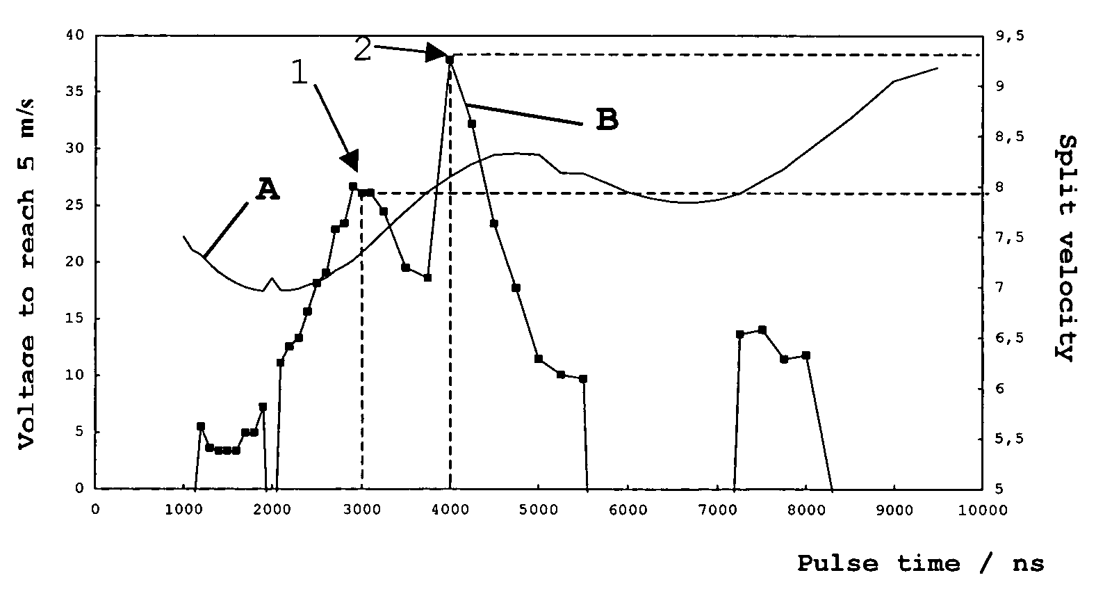
[0091]In this invention a method is described for making a waveform which creates larger drops including different droplets that merge on the nozzle plate 12 or in flight before hitting the printing substrate 15. In this embodiment, a waveform is generated optimising the velocity of the ink drops such that ink drops with different numbers of merged droplets have substantially the same velocity. If such multiple droplet drops with substantially equal velocity are ejected from different nozzles at substantially the same time, and travel the same distance to the printing substrate 15 they will land on the printing substrate after substantially the same time of flight.

[0092]In scanning printhead applications, with a relative movement between the printhead and the printing substrate, controlling the time of flight is crucial in ensuring a correct landing position of the drops, i.e. a correct dot positioning.

[0093]By way of example, the method described in this second embodiment of the in...


PUM


Abstract

A method provides an optimized set of waveforms for driving a printhead in greyscale printing wherein the waveforms include a pulse train of N pulses, wherein N is an integer, each pulse having a length LN, a time P(N-1)(N) existing between two adjacent pulses. The method includes: optimising a cost function that compares at least one ink ejection parameter such as drop velocity, difference in drop velocity, driving voltage, split velocity, number of split drops or drop placement error, with a printing speed parameter such as printing speed, the length LN of each pulse or the time P(N-1)(N) between two adjacent pulses.

Description

FIELD OF THE INVENTION[0001]The present invention relates to design method for optimising greyscale printing as well as an apparatus designed by the design method, e.g. a printer or a printer controller, that optimises greyscale printing and a method of operating such an apparatus. More specifically the invention is related to a method and apparatus for making a waveform to create ink drops that have the same velocity, especially for an inkjet printer, as well as a controller suitable for controlling a printer to generate such drops.BACKGROUND OF THE INVENTION[0002]Greyscale inkjet technology operates in a similar way to binary inkjet printing but has the ability to fire a range of drop sizes. The greyscale effect is achieved by firing multiple droplets from the same nozzle of a printhead in rapid succession, rather than a single droplet as occurs at binary applications. The salvo of droplets merges in flight to form inked areas, on the printing substrate, of variable size and there...

Claims


Application Information

Patent Timeline
Patent Type & Authority Patents(United States)
IPC IPC(8): B41J2/155
CPCB41J2/0458B41J2/04581B41J2/04588B41J2/2054B41J2/04595B41J2202/10B41J2202/06
Inventor VANHOOYDONCK, RUDI
Owner XAAR TECH LTD
Why Eureka
Try Eureka