Unlock instant, AI-driven research and patent intelligence for your innovation.

Module evaluation method and system

a module and evaluation method technology, applied in the field of module evaluation methods and systems, can solve the problems of not being performed, unable to quickly determine whether the use of the modular construction method is proper, and cannot be performed in an automatic manner, so as to quickly determine the overall effectiveness of the modular construction method. the effect of determining the overall effectiveness of the modular construction method

Inactive Publication Date: 2008-08-05
HITACHI LTD
View PDF11 Cites 2 Cited by
  • Summary
  • Abstract
  • Description
  • Claims
  • Application Information

AI Technical Summary

Benefits of technology

[0012]An object of the present invention is to realize a module evaluation method and system which can quickly determine overall effectiveness of the modular construction method in an automatic manner, taking into account the transportation cost and so on.
[0014]Thus, the present invention can realize the module evaluation method and system capable of quickly determining overall effectiveness of the modular construction method in an automatic manner, taking into account the transportation cost and so on.

Problems solved by technology

In the related art, however, determination of overall effectiveness taking into account the transportation cost and so on is not performed, and whether the use of the modular construction method is proper cannot be quickly performed in an automatic manner.

Method used


Image

  • Module evaluation method and system
  • Module evaluation method and system
  • Module evaluation method and system

Examples


first embodiment

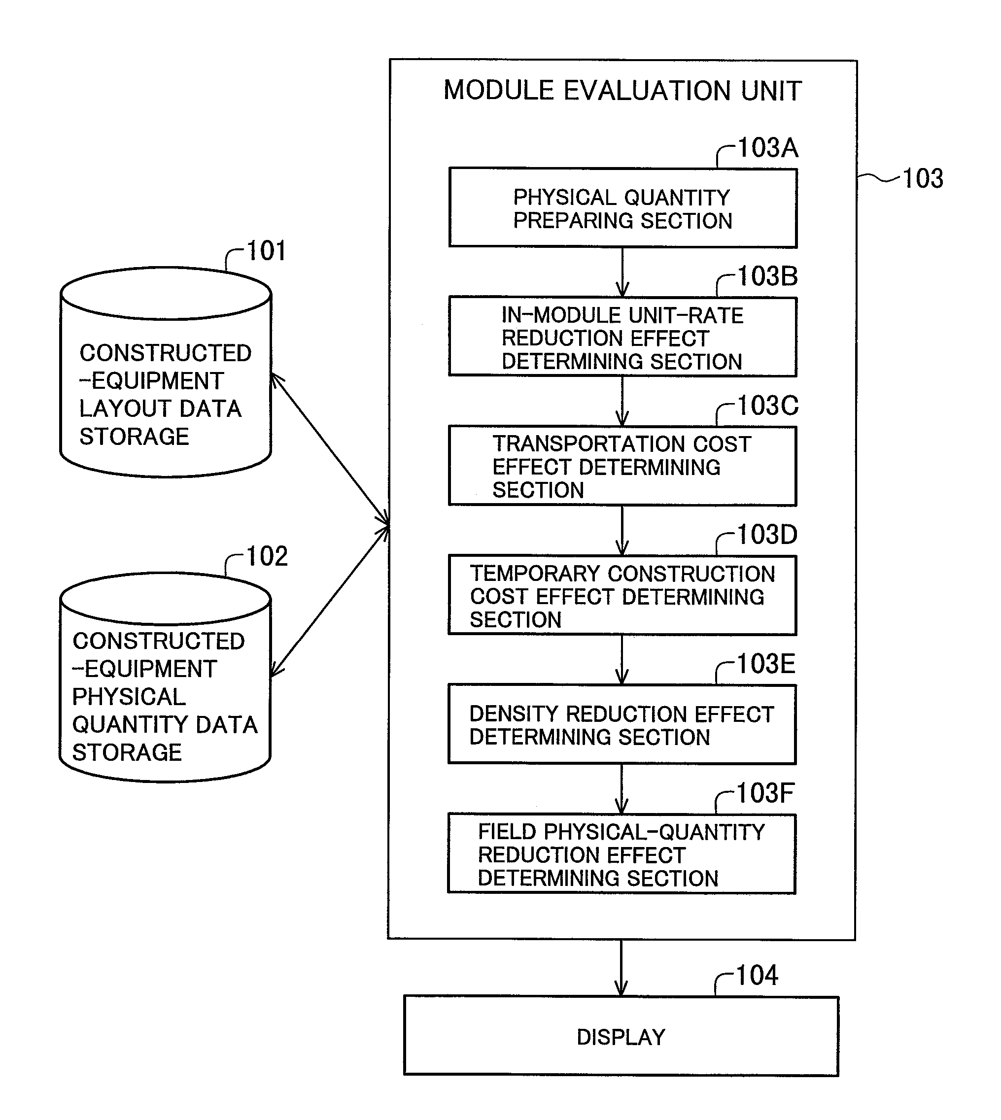
[0032]FIG. 1 is a block diagram of a module evaluation system to which is applied the present invention.

[0033]Referring to FIG. 1, the module evaluation system comprises a storage 101 for storing constructed-equipment layout data (including constructed-equipment arrangement schedule data for a region where arrangement of constructed equipment is scheduled, constructed-equipment modularization work data, and arrangement data for transportation of the modularized constructed-equipment to the arrangement scheduled region), a storage 102 for storing constructed-equipment physical quantity data (representing the number, sizes and weights of individual parts of the constructed equipment), a module evaluation unit 103, and a display 104.

[0034]The module evaluation unit 103 comprises a physical quantity data preparing section 103A, an in-module unit-rate reduction effect determining section 103B, a transportation cost effect determining section 103C, a temporary construction cost effect det...

second embodiment

[0083]the present invention will be described below.

[0084]The second embodiment of the present invention is intended to, when information for definition of a module is not included in the constructed-equipment layout data, make determination on effectiveness of the range of a designated imaginary module, or automatic determination on the effective range of modularization.

[0085]The basic configuration of the module evaluation system according to the second embodiment is the same as that of the first embodiment shown in FIG. 1, and therefore a detailed description of the system configuration is omitted here.

[0086]FIG. 13 is a flowchart of processing for determination of the modularization effectiveness in the second embodiment.

[0087]First, the range of a module frame is set in step 1201 of FIG. 13. Herein, the term “module frame” means an imaginary rectangular parallelepiped surrounding the constructed equipment, which is inputted by the user or set by the system and which is defined ...

third embodiment

[0100]FIG. 15 is a flowchart of processing for determination of the modularization effectiveness in the present invention, and FIG. 16 shows one example of a user display / operating screen.

[0101]As shown in FIG. 15, first, a target area is divided in the height direction as per upper limit size during the module transportation, and the target area is divided at constant intervals in a horizontal plane to form division frames in a grid pattern (step 1501, see FIG. 16). The smaller the division interval in the horizontal plane, the higher is the accuracy of the evaluation. A value of the division interval can be optionally set by the user.

[0102]Then, in step 1502, the man-hour density in each division frame is determined. The man-hour density is obtained by determining all the constructed equipment parts existing within each frame from the coordinate values of the constructed equipment parts, which are stored in the constructed-equipment arrangement data, and by summing up man-hour val...


PUM


Abstract

A module evaluation method and system which can quickly determine overall effectiveness of the modular construction method in an automatic manner, taking into account the transportation cost and so on. A module evaluation unit prepares constructed-equipment physical quantity data from constructed-equipment layout data, and determines an in-module unit-rate reduction effect resulted from executing construction work of the constructed equipment in the module in a factory where working efficiency is higher than a field. The module evaluation unit also determines a module transportation cost effect, a module temporary construction cost effect, and a density reduction effect that is resulted from a reduction of density in a space not occupied by a module with application of modularization and efficiency of installation work is increased. The module evaluation unit further determines a field physical-quantity reduction effect resulted from a reduction of physical quantity in the field and from a reduction of various overhead costs with application of the modularization. The determination results are displayed on a display.

Description

BACKGROUND OF THE INVENTION[0001]1. Field of the Invention[0002]The present invention relates to a module evaluation method and system for use with a modular construction method which is one of construction methods for plants, etc.[0003]2. Description of the Related Art[0004]The term “modular construction method” means a method for constructing and installing plant equipment through steps of prefabricating the equipment, such as piping and devices adjacent to each other, into modules, i.e., units of assembly constructed beforehand, transporting the modules to an installation site in a plant, and installing the modules in integral structure.[0005]By utilizing the modular construction method, assembly work can be performed in a factory where environment is better and the work cost is lower than those in the site or field, thus resulting in a reduction of the total cost due to a reduction of the assembly and installation cost, etc. Also, lump wok for installation of the individual modu...

Claims


Application Information

Patent Timeline
Patent Type & Authority Patents(United States)
IPC IPC(8): G06F19/00E04B1/00B23P21/00G06Q50/00G06Q50/08
CPCG06Q10/06
Inventor TAKADA, MASATOSHIMURAYAMA, KOICHIAKAGI, KENJI
Owner HITACHI LTD
Features
  • R&D
  • Intellectual Property
  • Life Sciences
  • Materials
  • Tech Scout
  • Unparalleled Data Quality
  • Higher Quality Content
  • 60% Fewer Hallucinations
Learn More