Aircraft and hybrid with magnetic airfoil suspension and drive

a technology of magnetic airfoil and hybrid aircraft, which is applied in the field of rotorcraft hybrid aircraft, can solve the problems of limiting the lift capability of rotorcraft, reducing the lift capacity of rotorcraft, and reducing the utilization of the center of the rotor area

Inactive Publication Date: 2008-08-12
NUNNALLY WILLIAM C
View PDF28 Cites 54 Cited by
  • Summary
  • Abstract
  • Description
  • Claims
  • Application Information

AI Technical Summary

Benefits of technology

[0005]It is therefore an object of the present invention to provide a rotorcraft or rotorcraft hybrid that combines the VTOL capabilities of a rotorcraft with the speed of a fixed wing aircraft.
[0006]It is a further object of the present invention to provide a craft of the above type that offers superior lift capabilities.
[0007]It is a further object of the present invention to provide a craft of the above type that offers horizontal speed that is not limited by the speed of the retreating blade.

Problems solved by technology

This means that the center of the rotor area is not being effectively utilized.
Similarly, because the rotor shaft is relatively small, the weight of the craft and any load carried may place significant stress on the shaft.
These disadvantages severely restrict the lift capabilities of rotorcraft.
Further, having the center of gravity displaced substantially below the center of lift leads to a relatively unstable configuration.
Further still, the horizontal speed of conventional rotorcraft is undesirably limited by the retreating blade limit.
Also, a tail rotor is needed for stability, and tail rotors of conventional helicopters suffer from a number of problems.
For example, mechanical linkages, such as drive shafts and gears, that mechanically couple tail rotors to main engines add unnecessarily to the weight of helicopters and can cause mechanical and reliability problems.
Still, conventional fixed wing aircraft typically lack VTOL capabilities.
While these are remarkable aircraft, they too suffer from a number of shortcomings.
For example, the vertical lift capabilities of these aircraft is quite limited and do not approach the vertical lift capabilities offered by many conventional helicopters, so they are poor candidates for transporting heavy payloads.
Also, these aircraft are relatively unstable during VTOL or VSTOL maneuvering.
Further still, mechanical linkages, such as drive shafts and gears, that mechanically couple lift fans and turbine engines can add unnecessarily to the weight of aircraft such as the Joint Strike Fighter and can lead to mechanical and reliability problems.

Method used


Image

  • Aircraft and hybrid with magnetic airfoil suspension and drive
  • Aircraft and hybrid with magnetic airfoil suspension and drive
  • Aircraft and hybrid with magnetic airfoil suspension and drive

Examples


Embodiment Construction

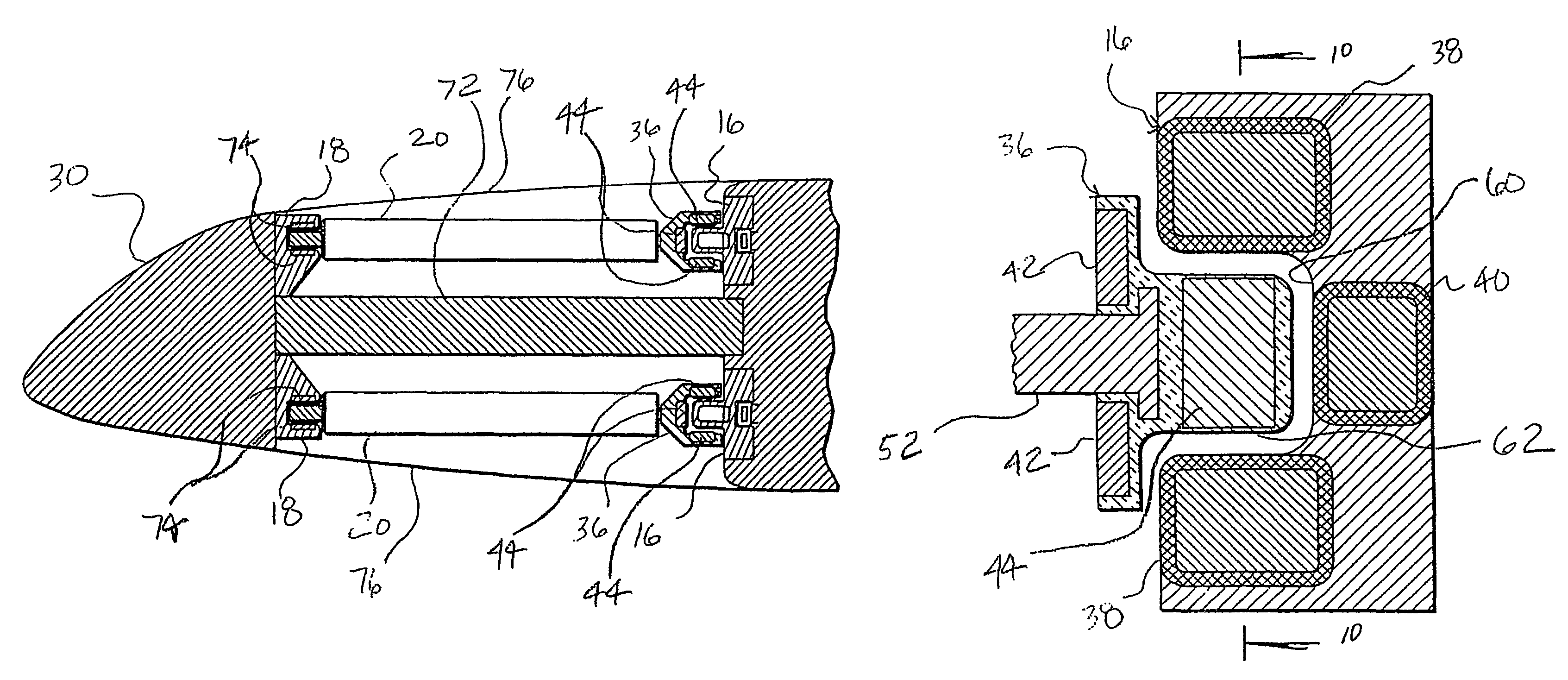
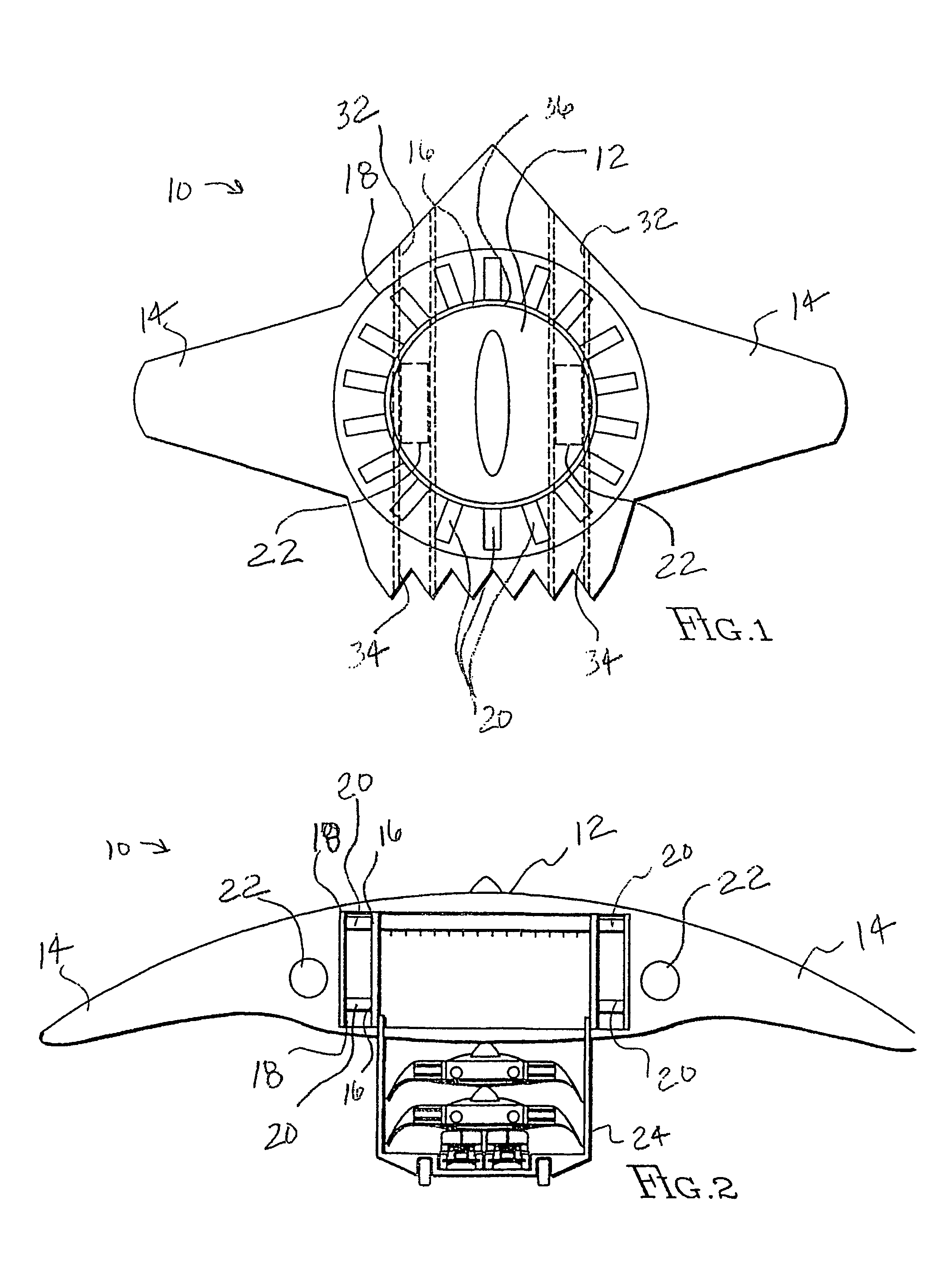
[0041]Referring to FIG. 1, the reference numeral 10 refers in general to an aircraft of the present invention. The aircraft has a fuselage 12, wings 14, inner and outer tracks or stators 16 and 18 encircling the fuselage, and airfoils 20 extending between the tracks 16 and 18. Means are provided for rotating the airfoils 20. Engines 22, such as turbine engines, may be provided.

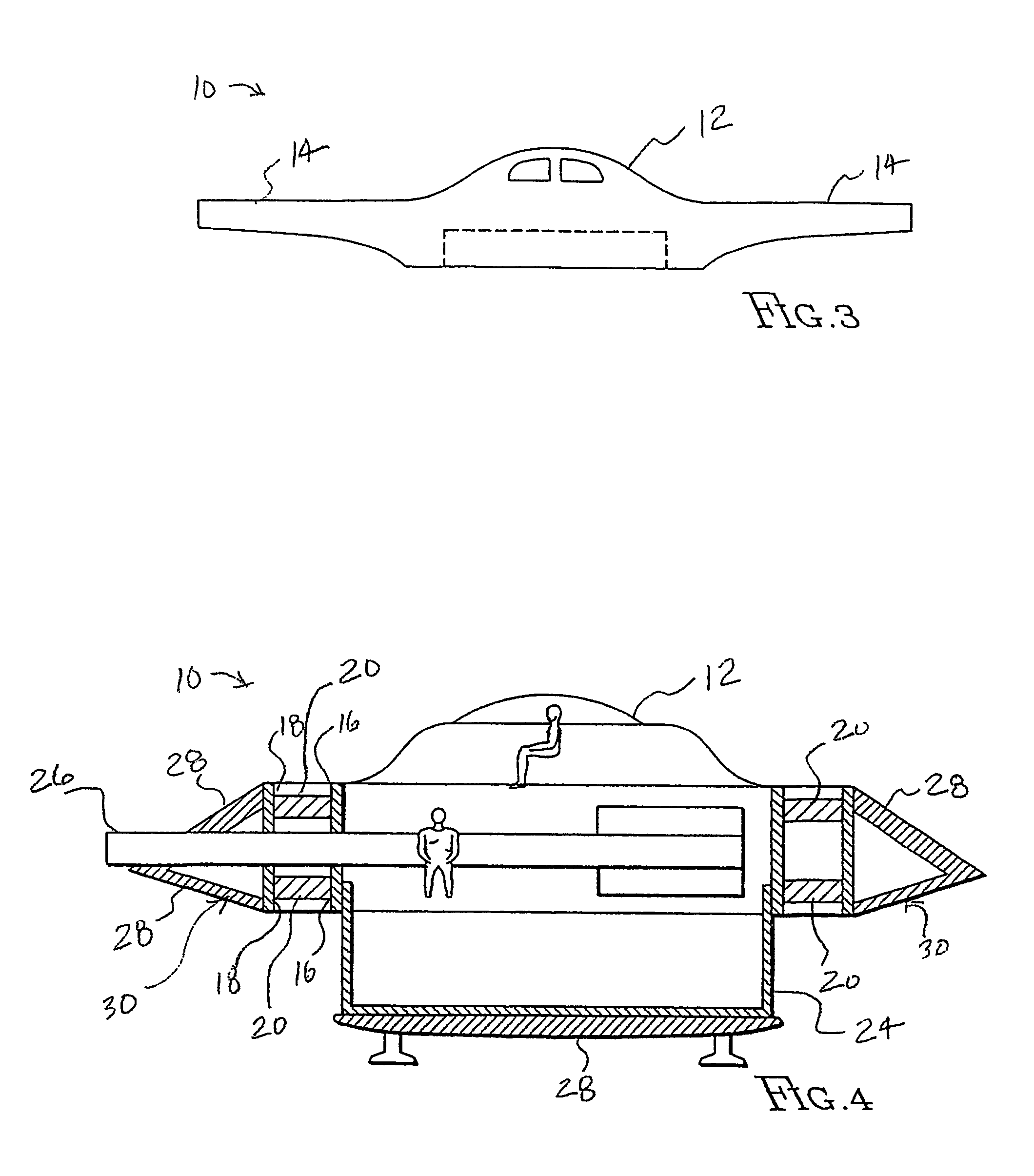
[0042]As illustrated in FIGS. 1-4, the fuselage 12 and wings 14 may take any number of shapes, sizes and configurations. Also, engines 22 may be affixed to the fuselage 12 or to the wings 14. Referring to FIG. 2, a cargo area 24 may form part of or be disposed below the fuselage 12. As shown in FIG. 3, in one alternate embodiment, the airfoils may be disposed below the fuselage 12 similar to a hovercraft. Although not clear from the schematic representation in FIG. 3, the top surface of the wing is shuttered for horizontal flight. As seen in FIG. 4, weapons 26, such as a large caliber gun, may be incorporated ...


PUM


Abstract

An aircraft is disclosed that comprises a fuselage with first and second wings non-rotatably secured to and extending from sides of the fuselage. Inner and outer tracks are secured to and encircle the fuselage, and airfoils are operably secured between the inner and outer tracks. Means are provided for rotating the airfoils. The means for rotating the airfoils may be comprised of first and second drive coils, and first and second alternators may be operably coupled to the first and second drive coils, respectively, to provide redundant power supplies. Permanent magnets in the rotor hub may be arranged in a Halbach array or may be arranged to provide a series of alternating, opposite magnetic poles. Separate drive and suspension coils may be provided in the stator. The concept may find further application in a lift fan or tail section of conventional aircraft. In that regard, a lift fan or tail section may be provided in which a stator magnetically levitates a lift fan rotor or tail rotor. The stator may include suspension coils and drive coils to eliminate the need for a drive shaft and gears to power the lift fan rotor or tail rotor.

Description

[0001]This application is a continuation-in-part of U.S. Provisional Patent Application No. 60 / 204,182, filed on May 15, 2000.BACKGROUND OF THE INVENTION[0002]This invention relates to aircraft, and more particularly, to a rotorcraft hybrid that incorporates a magnetic or electromagnetic vertical takeoff and landing (“VTOL”) system or an aircraft that uses a magnetic suspension and drive for a tail rotor or lift fan.[0003]Conventional helicopters or rotorcraft are versatile aircraft that allow for vertical takeoff and landing and that offer reasonable amounts of vertical lift and horizontal speed up to the retreating blade limit. The basic helicopter configuration is the result of mechanical evolution that applied the present state of the art over many years. While the conventional rotorcraft offers many advantages, it still suffers from a number of disadvantages. For example, rotor blades are long but provide meaningful lift over only a relatively short segment at the ends of the r...

Claims


Application Information

Patent Timeline
Patent Type & Authority Patents(United States)
IPC IPC(8): B64C27/20B64C29/00B64C39/00
CPCB64C27/20B64C39/001B64C29/0025
Inventor NUNNALLY, WILLIAM C.
Owner NUNNALLY WILLIAM C
Why Eureka
Try Eureka