Actuator structure and method for attaching a gear or pulley to lead screw

a technology of lead screw and actuator, which is applied in the direction of wing accessories, roofs, gearing, etc., can solve the problems of increasing the cost of the actuator and the products incorporating the actuator

Inactive Publication Date: 2008-08-12
DANA AUTOMOTIVE SYST GRP LLC
View PDF24 Cites 49 Cited by
  • Summary
  • Abstract
  • Description
  • Claims
  • Application Information

AI Technical Summary

Benefits of technology

[0007]An actuator in accordance with the present invention is advantageous as compared to existing lead screw actuators. In particular, the inventive actuator st...

Problems solved by technology

Each of these methods requires significant machining of the lead screw t...

Method used


Image

  • Actuator structure and method for attaching a gear or pulley to lead screw
  • Actuator structure and method for attaching a gear or pulley to lead screw
  • Actuator structure and method for attaching a gear or pulley to lead screw

Examples


Embodiment Construction

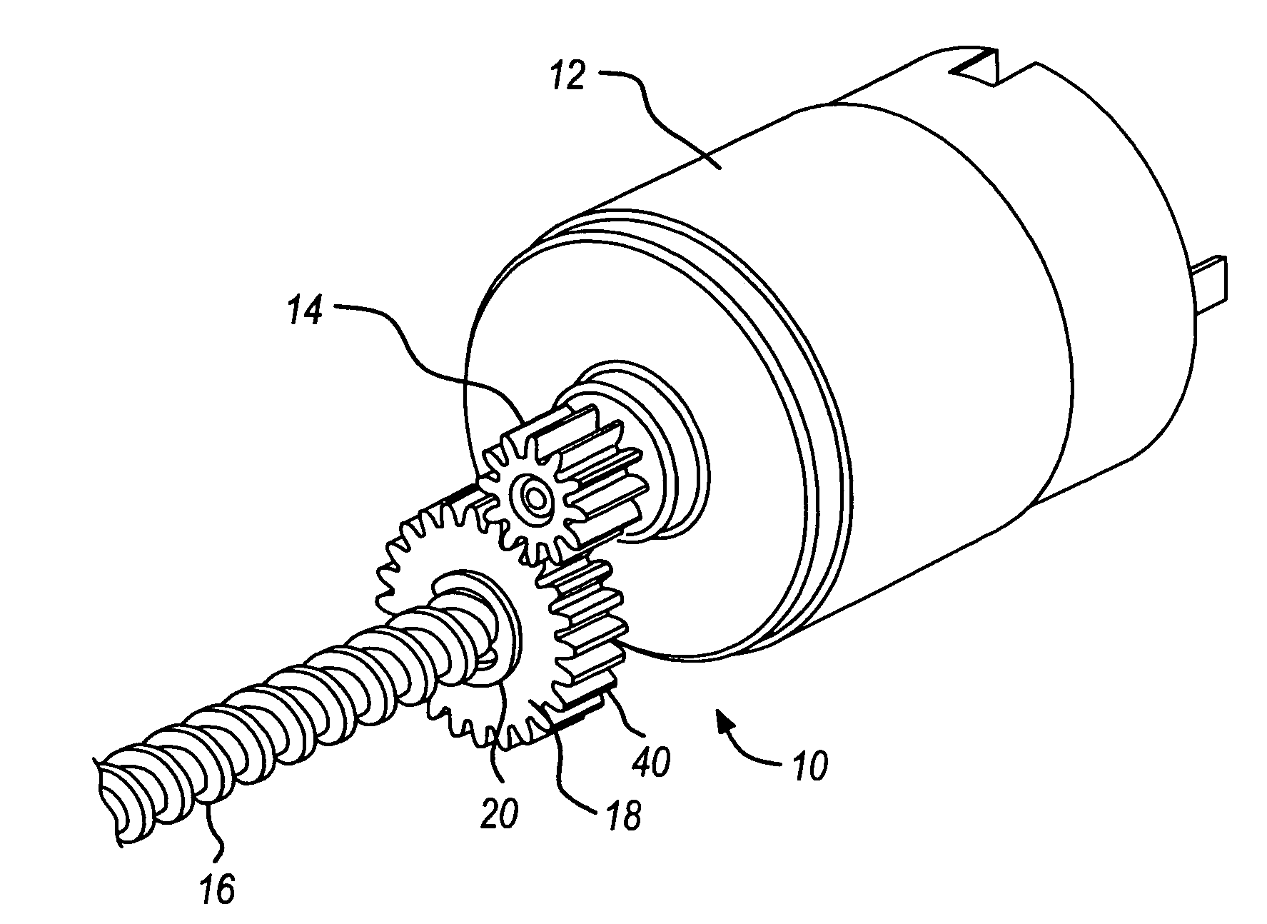
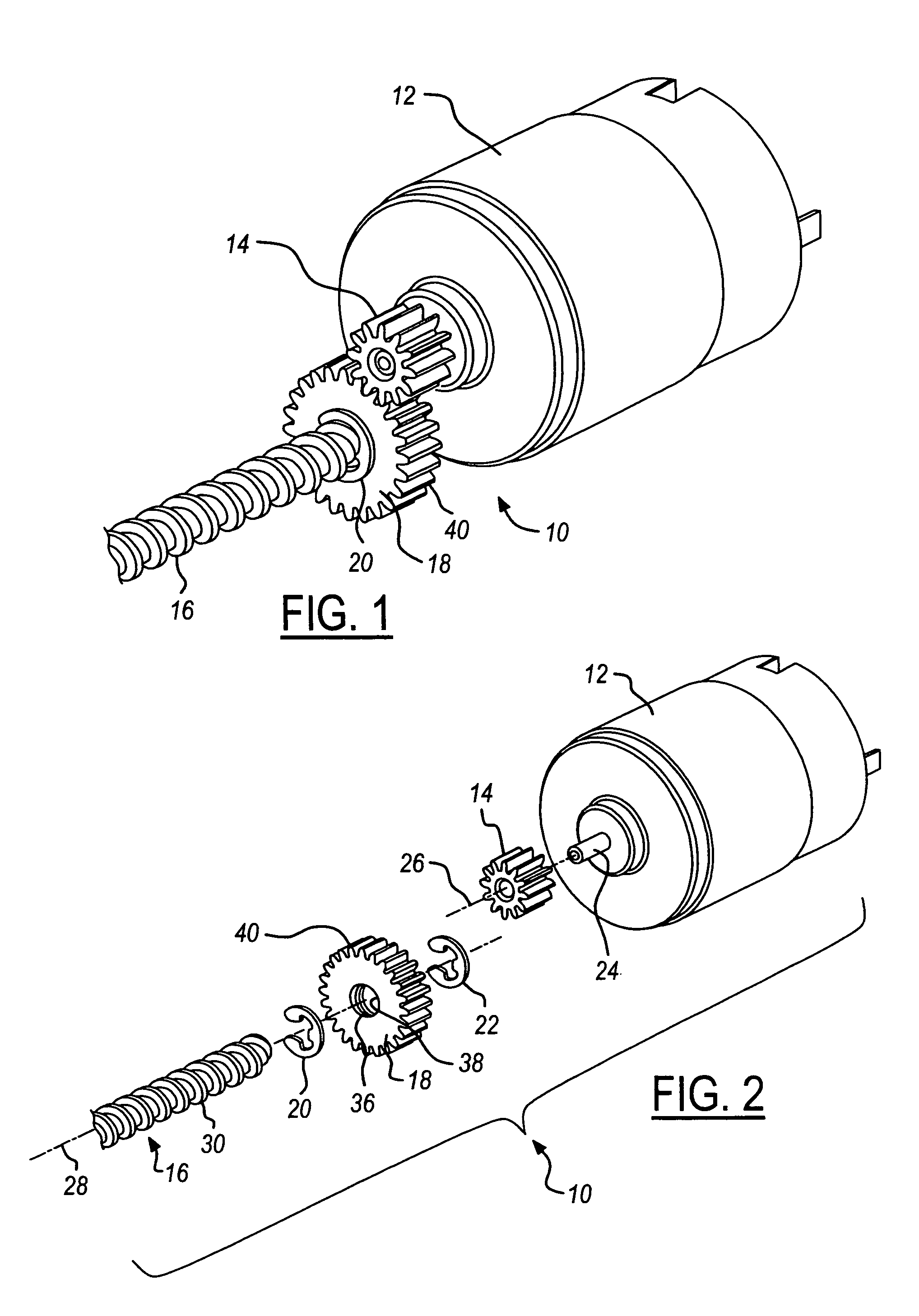
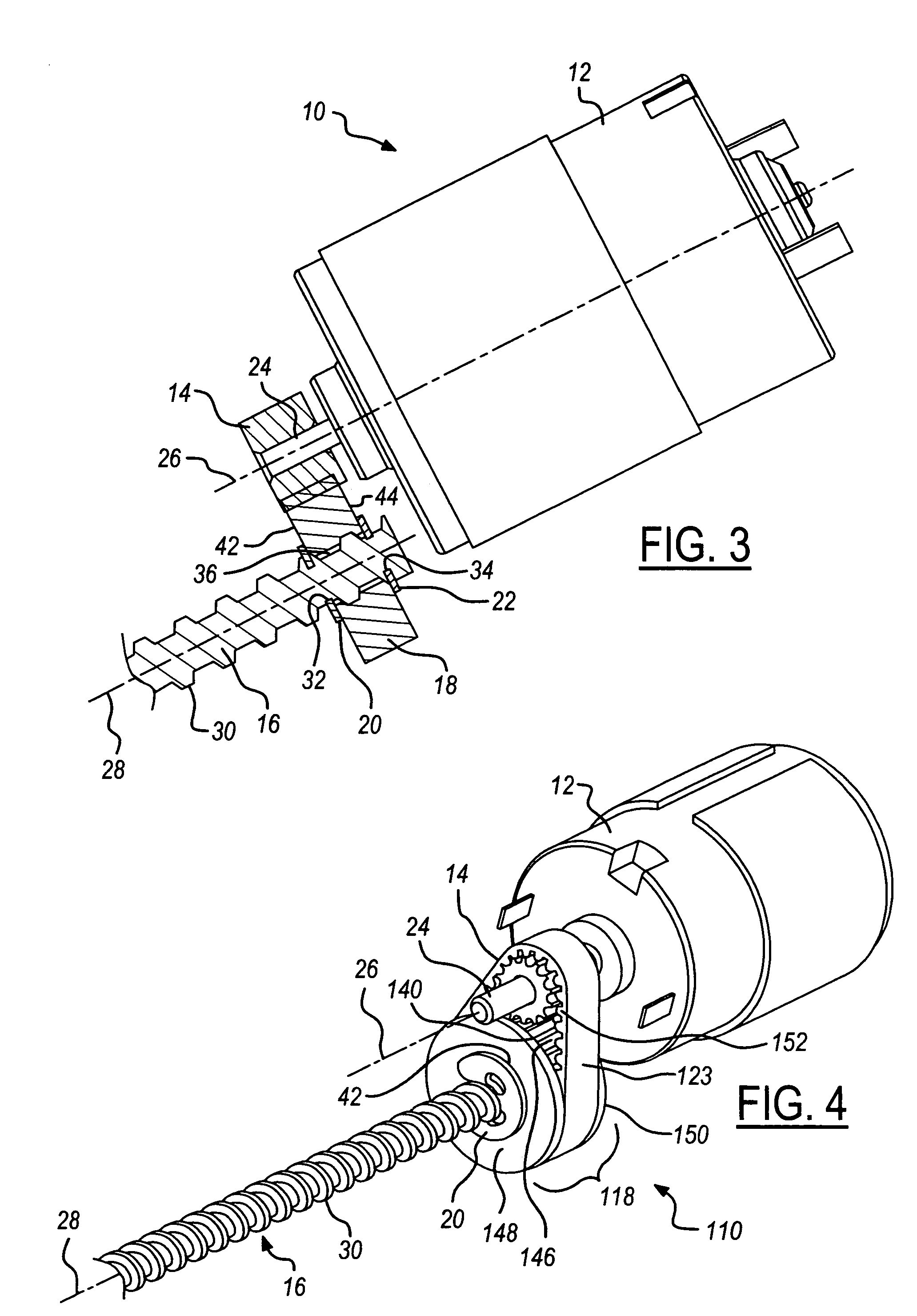
[0015]Referring now to the drawings wherein like reference numerals are used to identify identical components in the various views, FIGS. 1-3 illustrate a perspective view of an actuator 10 in accordance with one embodiment of the present invention. Actuator 10 is provided for use in a vehicle window assembly as discussed in greater detail hereinbelow. It should be understood, however, that actuator 10 may find use in a wide variety of applications. Actuator 10 may include a motor 12, a pinion gear 14, a lead screw 16, a driven member 18 and rings 20, 22.

[0016]Motor 12 is provided as a power source. Motor 12 is conventional in the art and may comprise an electric motor. As best shown in FIG. 2, motor 12 may have an output shaft 24 extending therefrom. Output shaft 24 is disposed about an axis of rotation 26. Output shaft 24 is provided to rotatably drive pinion gear 14.

[0017]Pinion gear 14 is provided to drive and transfer torque from output shaft 24 to driven member 18. Pinion gear...


PUM


Abstract

An improved lead screw actuator for use in applications including power vehicle windows is provided that significantly reduces the amount of machining that must be performed on the lead screw to enable secure attachment of a gear or pulley. The lead screw has a plurality of threads on its outer annular surface and a first and second axially spaced circumferential groove. A gear or pulley disposed about the lead screw has a female thread formed into an inner annular surface that is configured to engage at least one of the plurality of threads of the lead screw between the first and second grooves. A pair of rings are disposed within the first and second grooves in order to restrict axial movement of the gear or pulley on the lead screw.

Description

BACKGROUND OF THE INVENTION[0001]1. Field of the Invention[0002]The present invention relates to lead screw actuators and, in particular, to the connection of a driven member such as a gear or pulley to the lead screw.[0003]2. Discussion of Related Art[0004]Conventional methods for attaching gears or pulleys to a lead screw include a press-fit relationship, keying, splining, pinning or the use of set pins or set screws. Each of these methods requires significant machining of the lead screw that increases the cost of the actuator and products incorporating the actuator.[0005]The inventors herein have recognized a need for a lead screw actuator and a method for attaching a driven member to a lead screw that will minimize and / or eliminate the above-identified deficiencies.SUMMARY OF THE INVENTION[0006]The present invention provides an actuator for use in a vehicle window assembly or other applications. The actuator includes a motor having an output shaft extending therefrom and a lead ...

Claims


Application Information

Patent Timeline
IPC IPC(8): B60J7/00E05F11/34E06B3/32
CPCE05F15/652E05Y2900/55Y10T74/18792E05Y2201/696E05Y2201/72
Inventor WILSON, DARYLSTRONG, SCOTT L.
Owner DANA AUTOMOTIVE SYST GRP LLC
Why Eureka
Try Eureka