
Electrical connector assembly with reduced crosstalk and electromaganectic interference

a technology of crosstalk and electrical connectors, applied in the direction of coupling device connections, connection contact member materials, coupling protective earth/shielding arrangements, etc., can solve the problems of difficult and costly addition of coupling filter components to such miniaturized connectors, and the existence of never-ending noise or crosstalk between adjacent terminals. to achieve the effect of enhancing corsstalk compensation features

Inactive Publication Date: 2008-08-12
HON HAI PRECISION IND CO LTD
View PDF10 Cites 32 Cited by
  • Summary
  • Abstract
  • Description
  • Claims
  • Application Information

AI Technical Summary

Benefits of technology

The present invention provides an electrical connector assembly for high performance applications with enhanced cross-talk compensation features. The assembly includes an insulative housing, terminals, a printed circuit board, and a cable. The terminals have a mating portion, a tail portion, and an enlarged interconnecting portion. The terminals are arranged in a line along the transversal direction perpendicular to the mating direction. The enlarged interconnecting portions of the terminals are parallel to each other and separated by a dielectric at predetermined distance such that a capacitor is formed. The invention provides a simple and economical solution for high performance data transmission.

Problems solved by technology

Consequently, there exists a never-ending problem of noise or crosstalk between adjacent terminals, particularly in elongated straight / parallel portions of the terminals.
Adding such additional components as coupling filter components to such miniaturized connectors is difficult and costly.

Method used


Image

  • Electrical connector assembly with reduced crosstalk and electromaganectic interference
  • Electrical connector assembly with reduced crosstalk and electromaganectic interference
  • Electrical connector assembly with reduced crosstalk and electromaganectic interference

Examples


Embodiment Construction

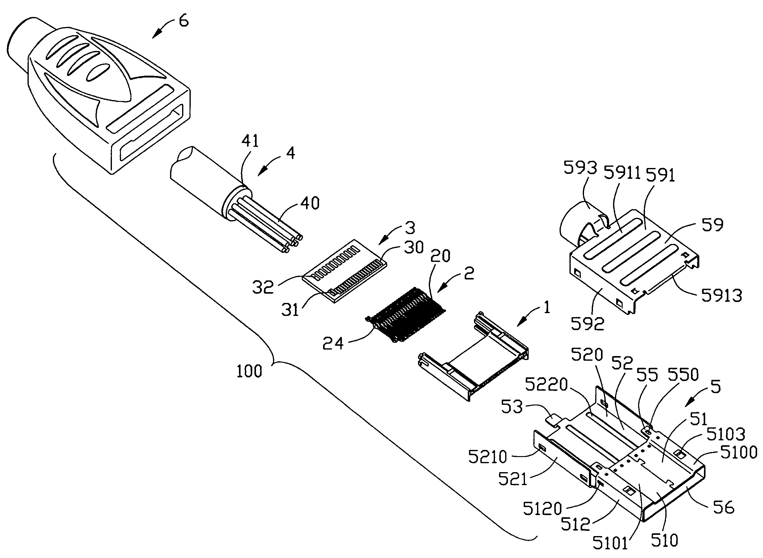
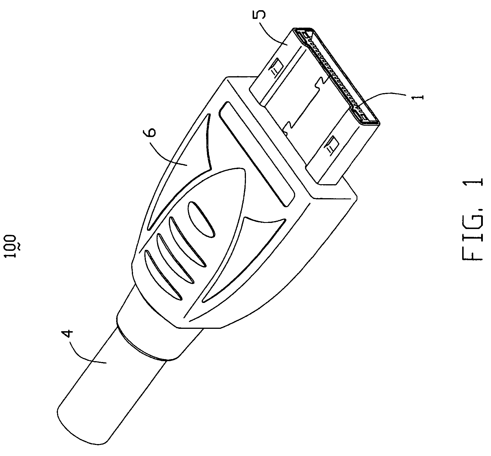
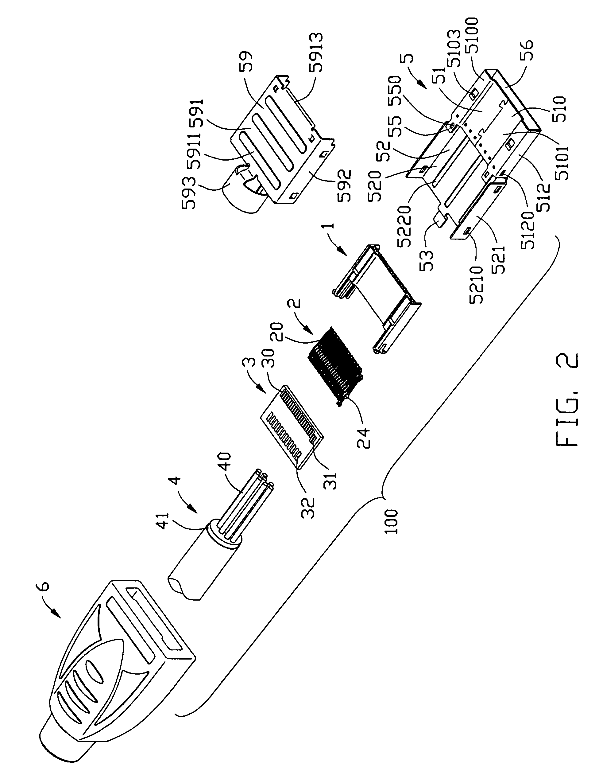
[0019]Referring to FIGS. 1-3, an electrical connector assembly 100 in accordance with the present invention defines a mating direction and a mating interface, and comprises an insulative housing 1, a plurality of terminals (or contacts) 2 received in the insulative housing 1 therein, a printed circuit bard 3 attached to the insulative housing 1 and electrically connected to the terminals 2, a cable 4 electrically connected to the printed circuit board 3, a metal shell 5 surrounding the insulative housing 1, the printed circuit board 3, and a protecting cover 6 partially enclosing the metal shell 5 and the front end of the cable 4.

[0020]Referring to FIGS. 2-5, the insulative housing 1 defines a base portion 10, and a pair of connecting portions 11 unitarily formed with and rearwardly extending from the base portion 10 along the mating direction, The insulative housing 1 is formed of an upper wall 12, a lower wall 13 extending parallel to the upper wall 12 and being shorter than the u...


PUM


Abstract

An electrical connector assembly (100) comprise an insulative housing (1) defining a mating direction, a plurality of terminals (2) received in the insulative housing (1) along the mating direction, a printed circuit board (3) attached to the insulative housing (1) and electrically connected to the terminals (2) and a cable (4) comprising a plurality of conductors (40) electrically attached to the printed circuit board (3). Each terminal (2) has a mating portion (23), a tail portion (21) and an enlarged interconnecting portion (22) connecting with the mating portion (23) and the tail portion (21).

Description

CROSS-REFERENCE TO RELATED APPLICATION[0001]This application is related to U.S. patent application Ser. No. 11 / 481,672, filed on Jul. 5, 2006, and entitled “ELECTRICAL CONNECTOR ASSEMBLY HAVING IMPROVED SHELL”, which has the same applicant and assignee as the present invention. The disclosure of related application is incorporated herein by reference.BACKGROUND OF THE INVENTION[0002]1. Field of the Invention[0003]The present invention relates generally to an electrical connector assembly, and more particularly to an electrical connector assembly for transmitting high-speed signals between two electrical devices.[0004]2. Description of Related Arts[0005]DisplayPort is a new digital display interface standard (approved in May 2006) put forth by the VESA (Video Electronics Standards Association). The standard defines a new license-free state-of-the-art digital audio / video interconnect, intended to be used primarily between a computer and its display-monitor, or a computer and a home-th...

Claims


Application Information

Patent Timeline
Patent Type & Authority Patents(United States)
IPC IPC(8): H01R12/00
CPCH01R13/6658H01R13/2442Y10S439/941
Inventor WU, JERRY
Owner HON HAI PRECISION IND CO LTD
Learn More