Electrical switching apparatus and method employing active acoustic sensing to detect an electrical conductivity fault of a power circuit

a technology of electrical switching apparatus and power circuit, which is applied in the direction of fault location by pulse reflection method, short-circuit testing, instruments, etc., can solve the problems of melted wires, unfavorable overload capability of circuit breaker, and unintentional arcing of arc fault in electrical circui

Active Publication Date: 2008-08-12
EATON INTELLIGENT POWER LTD
View PDF26 Cites 34 Cited by
  • Summary
  • Abstract
  • Description
  • Claims
  • Application Information

AI Technical Summary

Problems solved by technology

An arc fault is an unintentional arcing condition in an electrical circuit.
Arc faults can be caused, for instance, by worn insulation between adjacent bared conductors, by exposed ends between broken conductors, by faulty electrical connections, and in other situations where conducting elements are in close proximity.
During sporadic arc fault conditions, the overload capability of the circuit breaker will not function since the root-mean-squared (RMS) value of the fault current is too small to activate the automatic trip circuit.
The resulting temperature rise at this connection point can melt the wire's insulation and damage the receptacle.
During such periods, electrical and acoustic noise will be produced by the arc.
The problems associated with this proposal include: (1) the possibility of damage to the corresponding electrical circuitry; and (2) the possible introduction of a relatively high noise-to-signal ratio in the electrical circuit, which may distort the true signal.
Also, system stimulation and response monitoring may miss many loose intermittent events.

Method used


Image

  • Electrical switching apparatus and method employing active acoustic sensing to detect an electrical conductivity fault of a power circuit
  • Electrical switching apparatus and method employing active acoustic sensing to detect an electrical conductivity fault of a power circuit
  • Electrical switching apparatus and method employing active acoustic sensing to detect an electrical conductivity fault of a power circuit

Examples


example 1

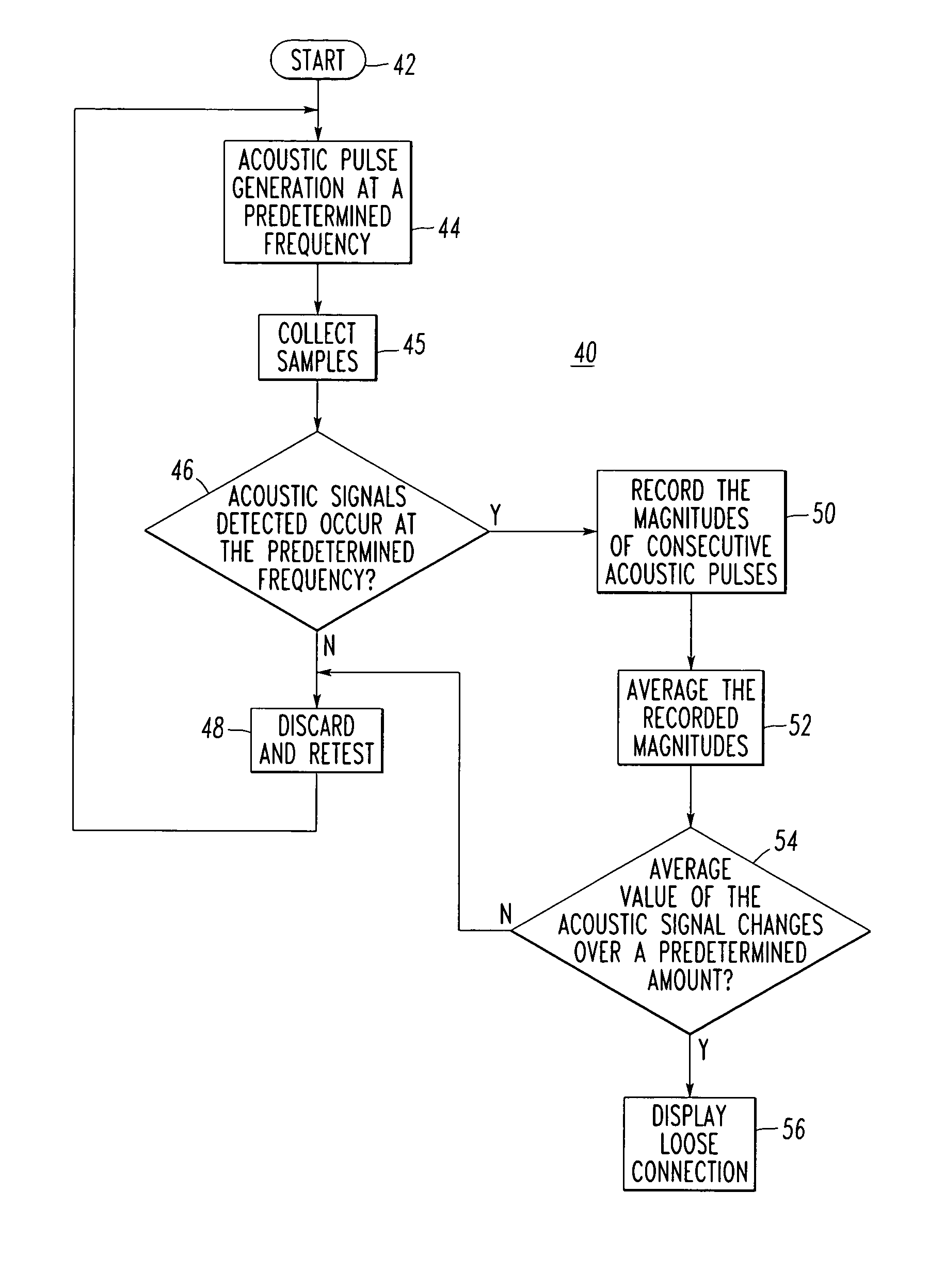
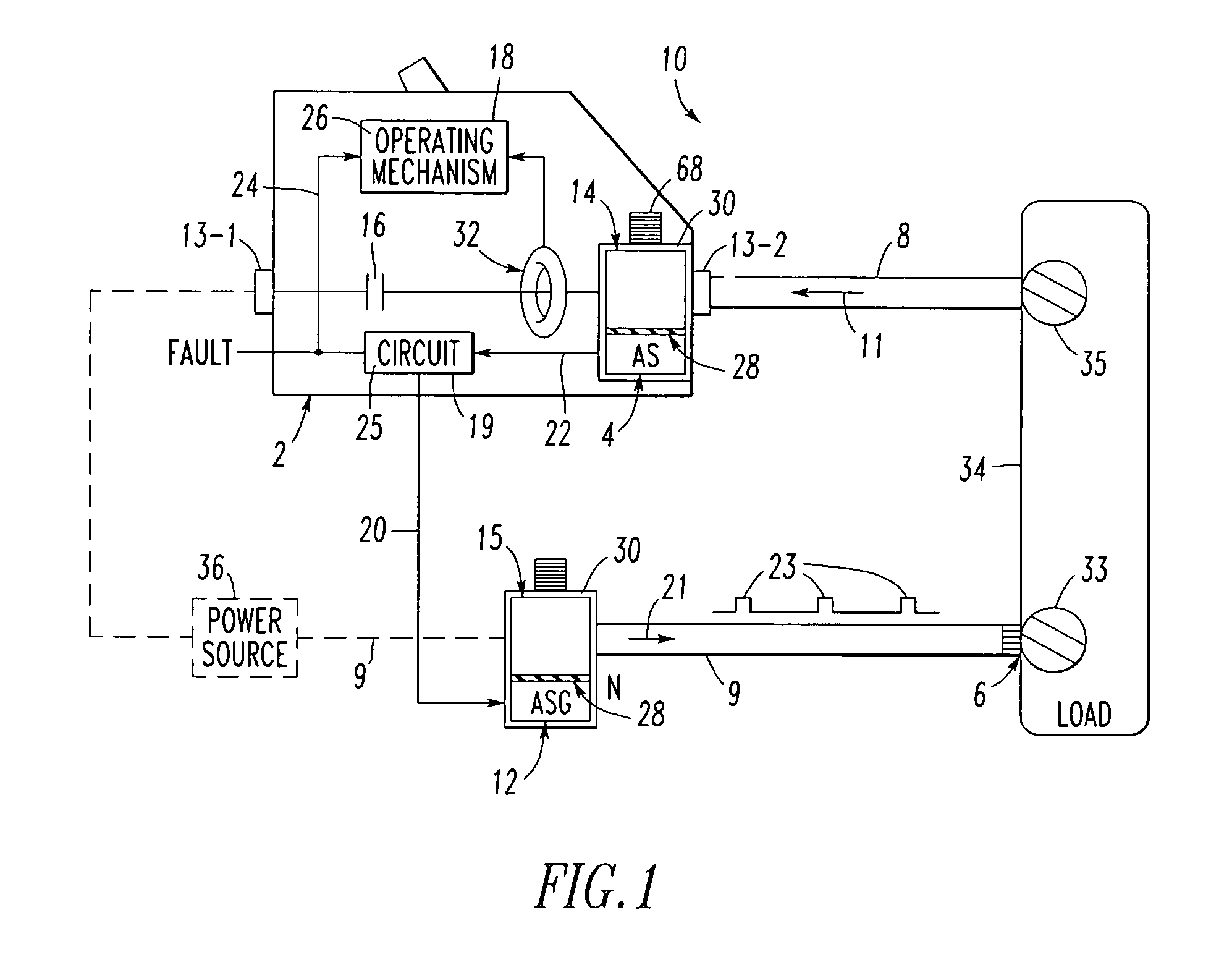
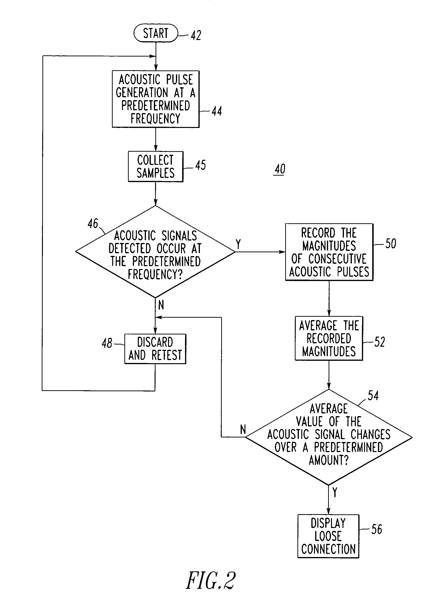
[0045]The circuit breaker 2 may be, for example, an arc fault circuit interrupter. The operating mechanism 18 may include a trip mechanism 26, and the circuit 19 may output the detected fault signal 24 as a trip signal to the trip mechanism 26 upon detecting the loose electrical connection condition 6 from the sensed acoustic signal 22, in order to interrupt the condition 6.

example 2

[0046]The example acoustic coupler 14 is preferably structured to match the acoustic wave-guide provided by the electrical conductor 8. The acoustic coupler 14 preferably includes suitable acoustic wave-guide properties that couple the acoustic signal 11 from the power circuit 10 to the acoustic sensor 4.

example 3

[0047]The acoustic coupler 14 may be an acoustic lug including a voltage (e.g., a line voltage from the line terminal 13-1) adapted to be electrically output to the power circuit 10. The acoustic lug preferably includes a suitable electrical insulator 28 (e.g., a relatively thin insulating polymer or ceramic) adapted to electrically insulate the acoustic sensor 4 from the voltage.


PUM


Abstract

A circuit breaker detects a loose electrical connection condition of a power circuit. The circuit breaker includes first and second lugs, first and second acoustic couplers acoustically coupled to the power circuit, separable contacts electrically connected in series between the first and second lugs, and an operating mechanism adapted to open and close the contacts. An acoustic generator is coupled to the second acoustic coupler and generates a first acoustic signal to the power circuit from the second acoustic coupler. An acoustic sensor is coupled to the first acoustic coupler and has a second acoustic signal which is operatively associated with the loose electrical connection condition. The acoustic sensor outputs a sensed acoustic signal. A circuit cooperates with the acoustic generator to generate the first acoustic signal, input the sensed acoustic signal, and detect the loose electrical connection condition therefrom.

Description

BACKGROUND OF THE INVENTION[0001]1. Field of the Invention[0002]This invention pertains generally to electrical switching apparatus and, more particularly, to circuit breakers that detect electrical conductivity faults, such as loose electrical connections, of a power circuit. The invention also pertains to a method for detecting electrical conductivity faults.[0003]2. Background Information[0004]Electrical switching apparatus include, for example, circuit switching devices and circuit interrupters such as circuit breakers, receptacles, contactors, motor starters, motor controllers and other load controllers.[0005]Circuit breakers are generally old and well known in the art. An example of a circuit breaker is disclosed in U.S. Pat. No. 5,341,191. Circuit breakers are used to protect electrical circuitry from damage due to an overcurrent condition, such as an overload condition or a relatively high level short circuit or fault condition. Molded case circuit breakers, for example, inc...

Claims


Application Information

Patent Timeline
Patent Type & Authority Patents(United States)
IPC IPC(8): G01R31/11G01R31/50
CPCG01R31/026G01R31/54G01R31/52G01R31/50
Inventor ZHOU, XIN
Owner EATON INTELLIGENT POWER LTD
Why Eureka
Try Eureka