Buoyant cable antenna configuration and system

a technology of abu-cable antenna and abu-cable, which is applied in the direction of antenna details, antenna adaptation in movable bodies, antennas, etc., can solve the problems of limiting the use of horizontal antenna elements, interrupting transmissions, and affecting so as to achieve the effect of increasing the stability of one or more antennas

Inactive Publication Date: 2008-08-12
UNITED STATES OF AMERICA
View PDF8 Cites 5 Cited by
  • Summary
  • Abstract
  • Description
  • Claims
  • Application Information

AI Technical Summary

Benefits of technology

[0016]It is another object of the present invention to use a coil form to provide a suitable configuration for a platform that permits use of a wide range of different types of antennas.
[0017]It is yet another object of the present invention to provide an improved towed platform which substantially avoids the problems of waves washing over the platform which cut off communication signals.
[0018]It is yet another object of the present invention to provide an improved configuration that provides a stable antenna support in the water.
[0024]A method is provided for the buoyant cable system which may comprise steps such as, for instance, providing a transmission line that may be spooled out from a submerged vessel, providing that one or more buoyant portions of the transmission line are sufficiently buoyant to cause the transmission line to float to a surface of the water, weighting at least one portion of the transmission line to form at least one weighted keel portion of the transmission line, providing that the one or more buoyant portions of the transmission line and the weighting of the weighted keel portion substantially determines a maximum water depth of the weighted keel portion, and / or providing a buoyant platform section of the transmission line on an opposite side of the weighted keel portion with respect to the one or more buoyant portions of the transmission line, and / or providing one or more antennas on the buoyant platform section of the transmission line for extending above the surface of the water.
[0026]The method may further comprise positioning a rotary connector between the weighted keel portion and the buoyant portions of the transmission line. In one preferred embodiment, the method may also comprise providing two opposing buoyant outrigger curve portions of the transmission line roughly adjacent or near the weighted keel portion to provide additional stability of the one or more antennas.

Problems solved by technology

Sea water attenuation, antenna gain and frequency patterns limit the use of a horizontal antenna element.
The waves may frequently wash over the cable thereby interrupting transmissions.
This is especially likely to happen when the platform is being towed through the water.
Moreover, this type of towed platform is quite limited in the types of antennas that can be utilized therewith.
Other towed platforms could be used, but are not capable of being deployed and retrieved into a submerged vessel.
The limited antenna gain pattern limits the reception capability of the buoyant cable antenna.
The solutions to the above-described problems have been long sought without success.

Method used


Image

  • Buoyant cable antenna configuration and system
  • Buoyant cable antenna configuration and system
  • Buoyant cable antenna configuration and system

Examples


Embodiment Construction

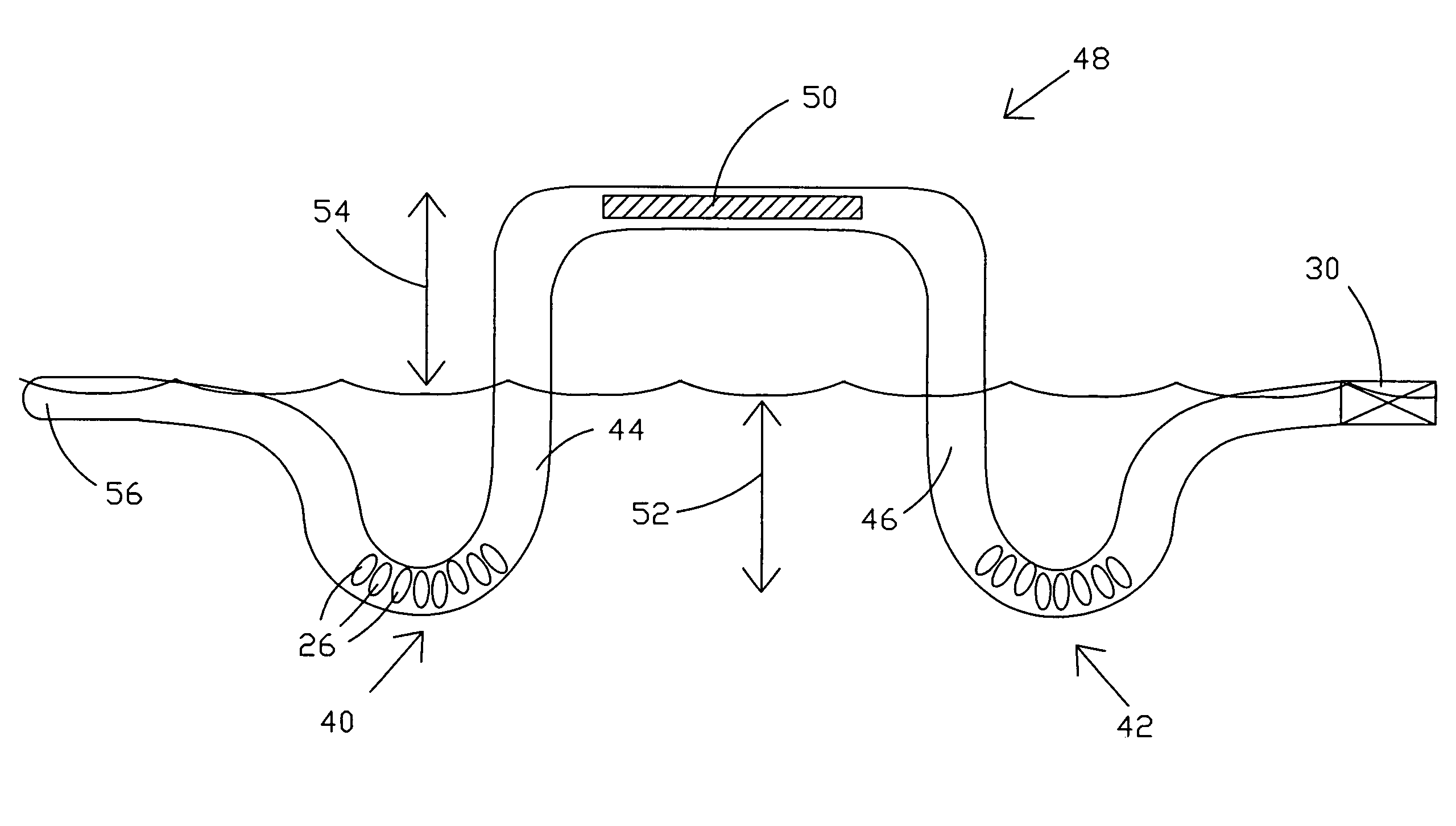
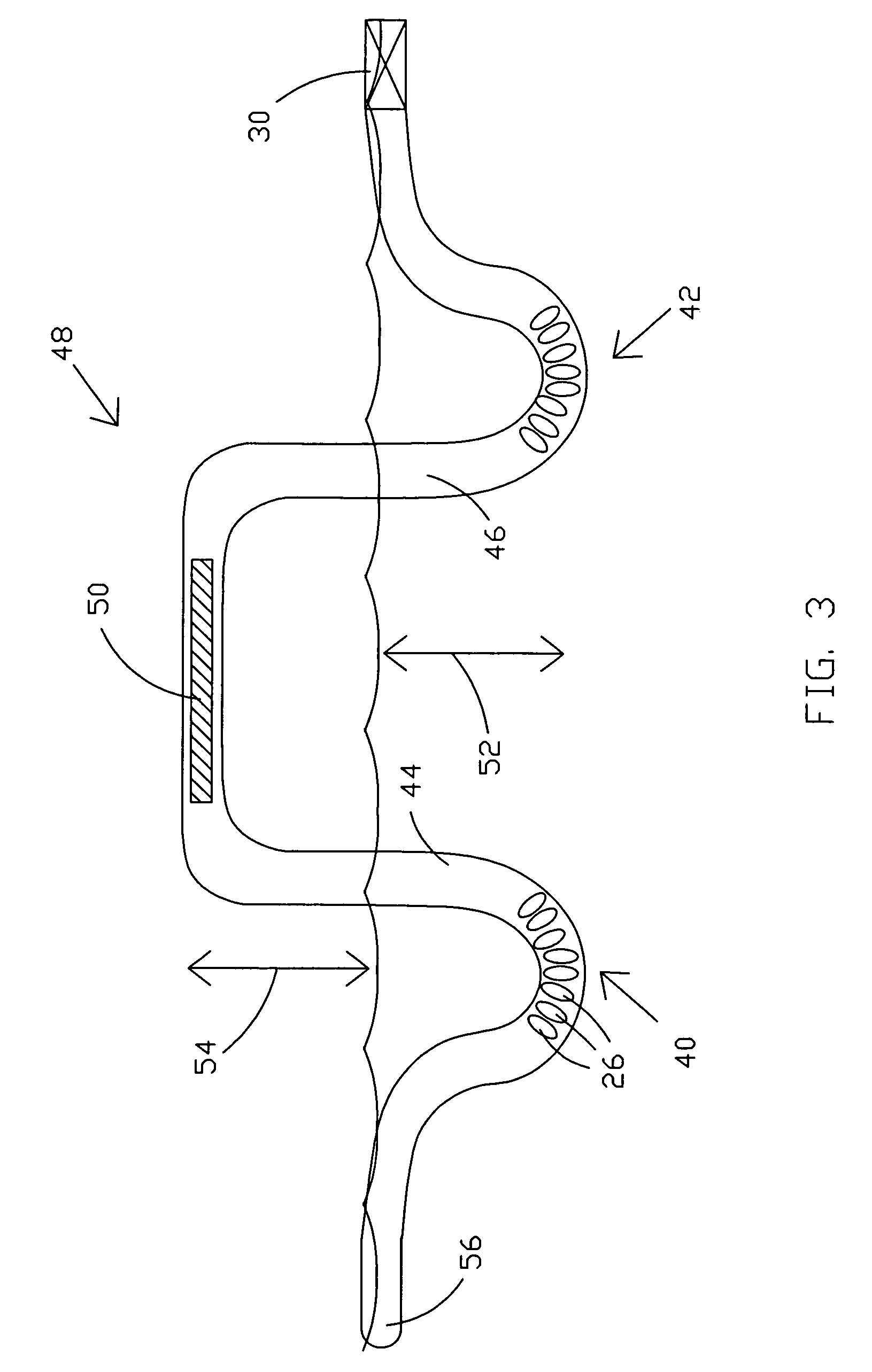
[0031]The present invention provides a towed platform for an antenna that would be towed at the end or roughly near the end of the buoyant cable transmission. The weighted keel discussed in more detail below would provide vertical / horizontal stability for antennas of many types (i.e. monopole, dipole, helical, spiral, patch). When the assembly is deployed by a submerged vessel, the buoyant antenna assembly employs the use of one or more weighted keels to assure proper position on the sea water surface and a rotary joint to nullify the towing effects of the transmission line. Increased frequency band reception, antenna frequency gain and pattern enhancement are advantages and new features. Flexible shape permits passage through deployment mechanisms.

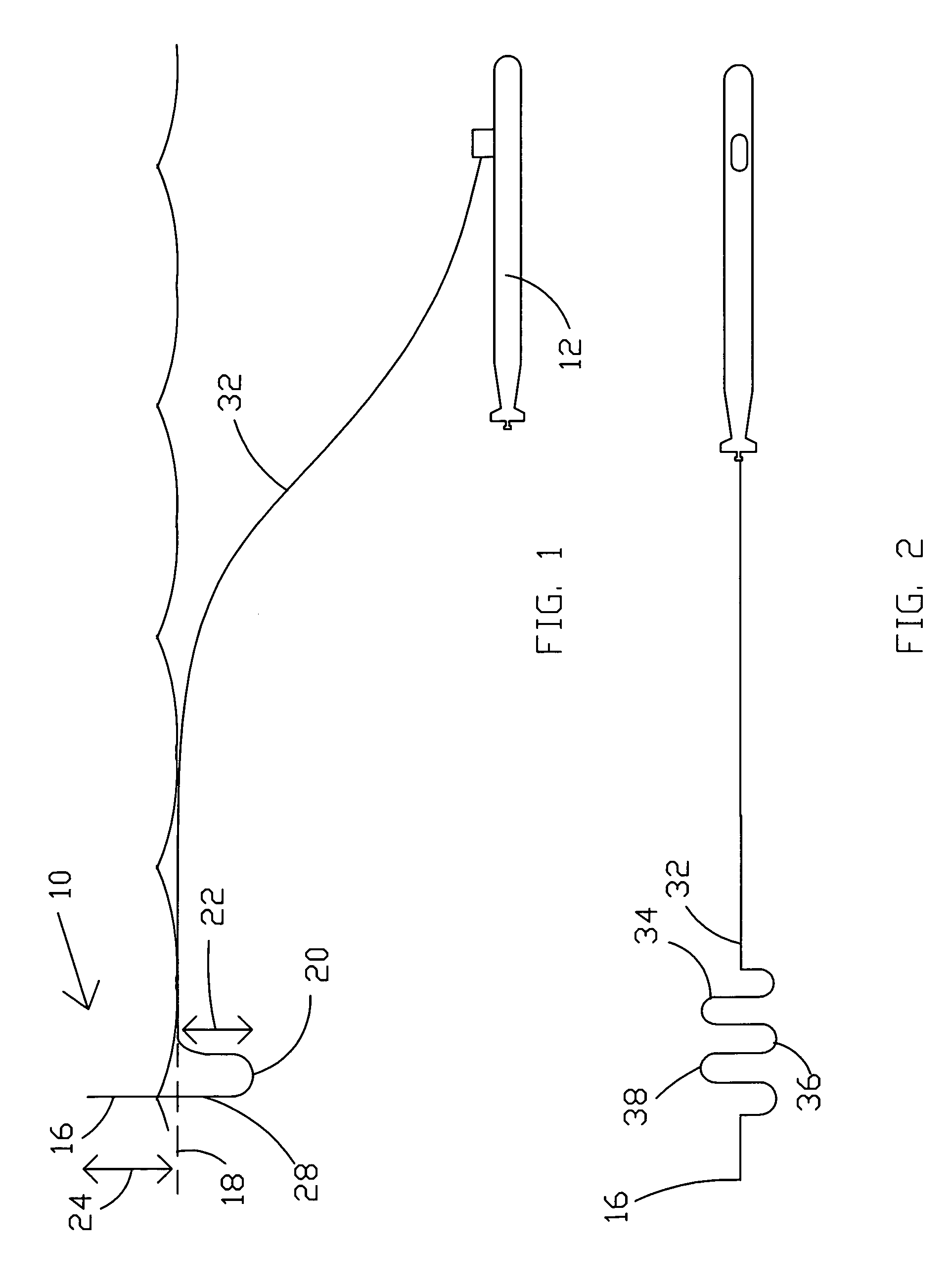
[0032]Referring now to the drawings, and more particularly to FIG. 1, there is shown one possible embodiment of a towed buoyant platform system 10 for use with submerged submarine 12 in accord with the present invention. Other shapes and ...


PUM


Abstract

A buoyant cable system and method is provided with a towed transmission line and antenna platform that may be deployed into the water from a submerged submarine so that the antenna extends above the surface of the water. The cable system preferably utilizes a flexible weighted keel formed in a section of the transmission line. A buoyant section of transmission line extends upwardly from the depth of the weighted keel to support one or more antennas above the surface of the water. In another embodiment, a plurality of weighted keels may be formed in sections of the transmission line whereby an inverted U-shaped buoyant portion extends upwardly from the depth of weighted keel to act as the support for a horizontally oriented antenna.

Description

STATEMENT OF GOVERNMENT INTEREST[0001]The invention described herein may be manufactured and used by or for the Government of the United States of America for governmental purposes without the payment of any royalties thereon or therefore.CROSS-REFERENCE TO RELATED APPLICATIONS[0002]The instant application is related to three co-pending U.S. patent application Ser. Nos. entitled BUOYANT CABLE ANTENNA SYSTEM AND METHOD WITH ARTICULATING BLOCKS 11 / 650,763, SERPENTINE BUOYANT CABLE ANTENNA SYSTEM 11 / 650,764, and BUOYANT CABLE ANTENNA SYSTEM 11 / 650,761, having the same filing date.BACKGROUND OF THE INVENTION[0003](1) Field of the Invention[0004]The present invention relates generally to a buoyant cable antenna system and, in a more particular preferred embodiment, to a buoyant cable antenna system with extended frequency range capability.[0005](2) Description of the Prior Art[0006]Present buoyant cable antenna systems which serve as a towed platform by underwater vehicles such as submar...

Claims


Application Information

Patent Timeline
Patent Type & Authority Patents(United States)
IPC IPC(8): H01Q1/34
CPCH01Q1/34
Inventor PICKREIGN, LEGAL REPRESENTATIVE, HEIDI R.GERHARD, ERICH M.
Owner UNITED STATES OF AMERICA
Why Eureka
Try Eureka