
System and method for positively discharging crop residue from a combine

a technology of positive discharge and combine, which is applied in the direction of mowers, agriculture tools and machines, agriculture, etc., can solve the problems of limited material handling capacity or rate, crank mechanism add complexity and vibration, and slow operation, so as to achieve faster drying, reduce or shorten the cutting of stubble, and increase the yield of straw

Active Publication Date: 2005-05-12
BLUE LEAF I P
View PDF19 Cites 25 Cited by
  • Summary
  • Abstract
  • Description
  • Claims
  • Application Information

AI Technical Summary

Benefits of technology

[0021] It is contemplated that the conveying mechanism can be of variable speed to accommodate different types of crop residue. For example, the conveying mechanism can include a sensor device or devices for detection of predetermined parameters such as variables relating to or representative of conditions of the crop residue being delivered, such as differential weight, volume, or moisture contents of the crop residue. Thus, the conveying mechanism can be adjusted, either automatically or manually, to accommodate any type of crop residue having any type of characteristic, thereby ensuring precise, efficient, and consistent crop residue discharge.
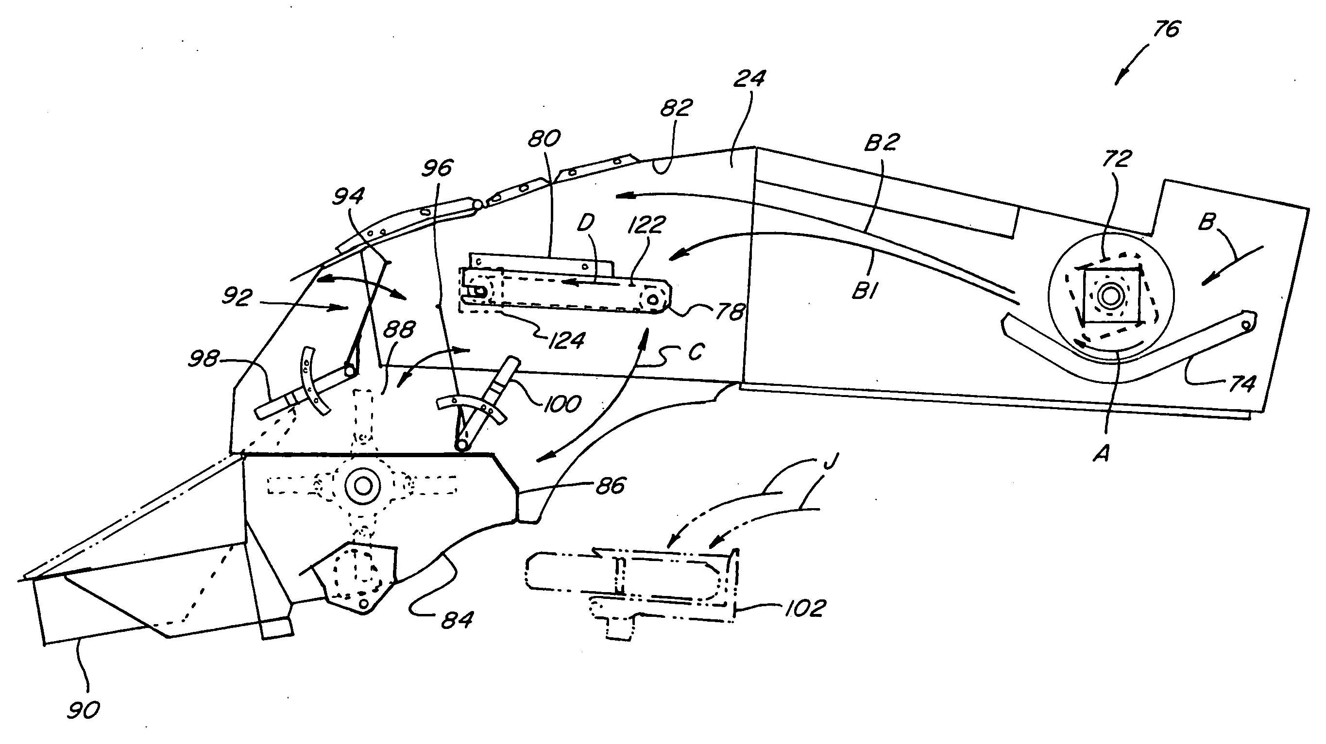
[0023] In a further embodiment of the present invention, the system is configurable to discharge crop residue directly out the rear of the combine, in a windrow formation, to the harvested field behind or below the combine. Additionally, the system can be configured to deposit the straw on the field in a substantially continuous, cohesive, air permeable mat, which is laid more on the stubble on the field in contrast to being driven into and integrated into the stubble. As a resultant advantage, there can be greater air flow through and beneath the stubble for faster drying. As another advantage, the stubble can be cut lower or shorter, for greater straw yield, because the rakes of a straw baler can be set higher as a result of the straw lying more on the stubble as opposed to being more integrated into the stubble.
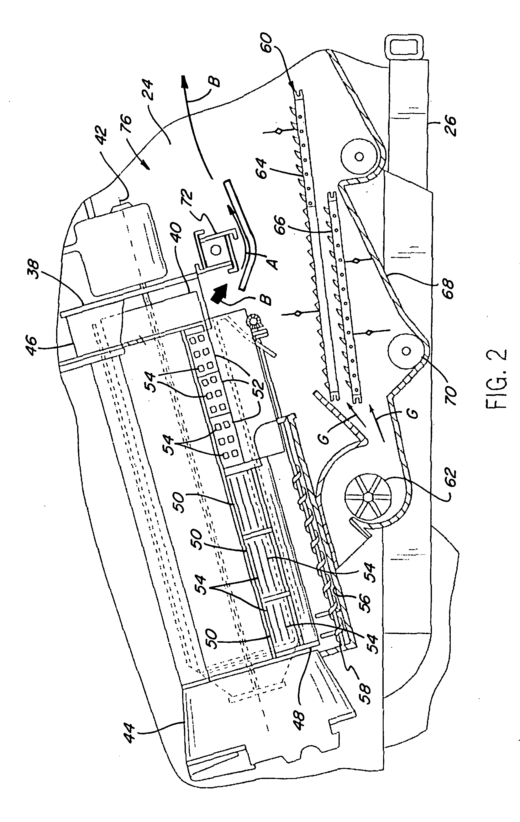
[0024] In yet an additional embodiment of the present invention, the system is configurable so as to reduce or even alleviate crop residue blockages at the rear of the combine, thereby decreasing combine down time and increasing harvesting productivity and customer satisfaction. This is a result, at least in part, of a capability of the present system to convey and guide the crop residue more uniformly or consistently to a selected processing mechanism at or in the rear of the combine, such as a straw chopper, spreader or the like, without heavier or larger elements of the straw, such as wads, vines, and the like, falling onto or into a chaff spreader typically located forwardly of a straw chopper and / or spreader and an outlet used for windrowing. In this latter regard, the conveying mechanism can be positioned partially above the chaff spreader. Also, the conveying mechanism is preferably positioned in rearwardly converging or tapering relation to a crop residue hood ceiling of the body of the combine located above the conveyor mechanism, such that as the crop residue is conveyed rearwardly by the conveying mechanism, it is merged and integrated with lighter or other portions of the crop residue flow which remain airborne longer and thus are not deposited on the conveyor surface. This convergence or taper also reduces the vertical extent or height of the rear end of the space through which the crop residue is conveyed and merged, such that the overall vertical extent or height profile of the flow of the crop residue will be reduced and made more uniform and consistent as it is directed to the processing mechanism or outwardly from the combine for windrowing. In this latter regard, as a result, the crop residue flows or is discharged from the combine in essentially a continuous, cohesive mat, which can be lowered onto field stubble so as to lie thereon and more effectively and rapidly dry, so as to be capable of being raked up and baled sooner compared to straw which is forcefully propelled downwardly and integrated into the stubble.

Problems solved by technology

Generally, straw walkers, which involve crank mechanisms for conveying the crop residue rearwardly through a combine, are relatively slow in operation and thus have a limited material handling capability or rate.
The crank mechanisms add complexity and vibration.
While conventional discharge beaters have adequately conveyed or discharged crop residue to the rear of conventional rotary combines, they are often less than satisfactorily able to consistently deliver crop residue to the residue handling systems of today's new, improved combines.
For example, as capacities of modern combines and the volume of material the combine handles per unit of time have continued to increase, conventional discharge beaters have been unable to precisely and consistently throw the increased amounts of crop residue to the rear of the combine.
Accordingly, use of a conventional discharge beater alone has been found to be insufficient for many newer combine applications.
To summarize, although technological advances have improved upon some of the inadequacies of conventional discharge systems, problems remain.
One problem is that as crop handling capacities of combines have increased, the volume of crop residue that must be conveyed, thrown or propelled rearwardly within the body of the combine, has also increased.
A problem that has been encountered in regard to these latter applications is that varying moisture content of crop residue, and different types of crop residue, result in a wide range of possible weights of the crop residue and thus the effort needed to properly deliver it to the rear of the combine.
Accordingly, if crop residue falls short of the rear of the combine, blockages and interference with the operation of the chaff handling system can occur, thereby causing significant combine down time, decreases in harvesting productivity, and increases in operator and owner dissatisfaction and component failure.
This can result in longer drying times, and to bale the straw the tines of the straw rake must pass through the stubble close to the ground for removing the straw from the stubble.
Accordingly, the drawbacks of the conventional systems and methods for discharging crop residue from a combine have been known within the industry without any marked improvement to date.

Method used


Image

  • System and method for positively discharging crop residue from a combine
  • System and method for positively discharging crop residue from a combine
  • System and method for positively discharging crop residue from a combine

Examples


Embodiment Construction

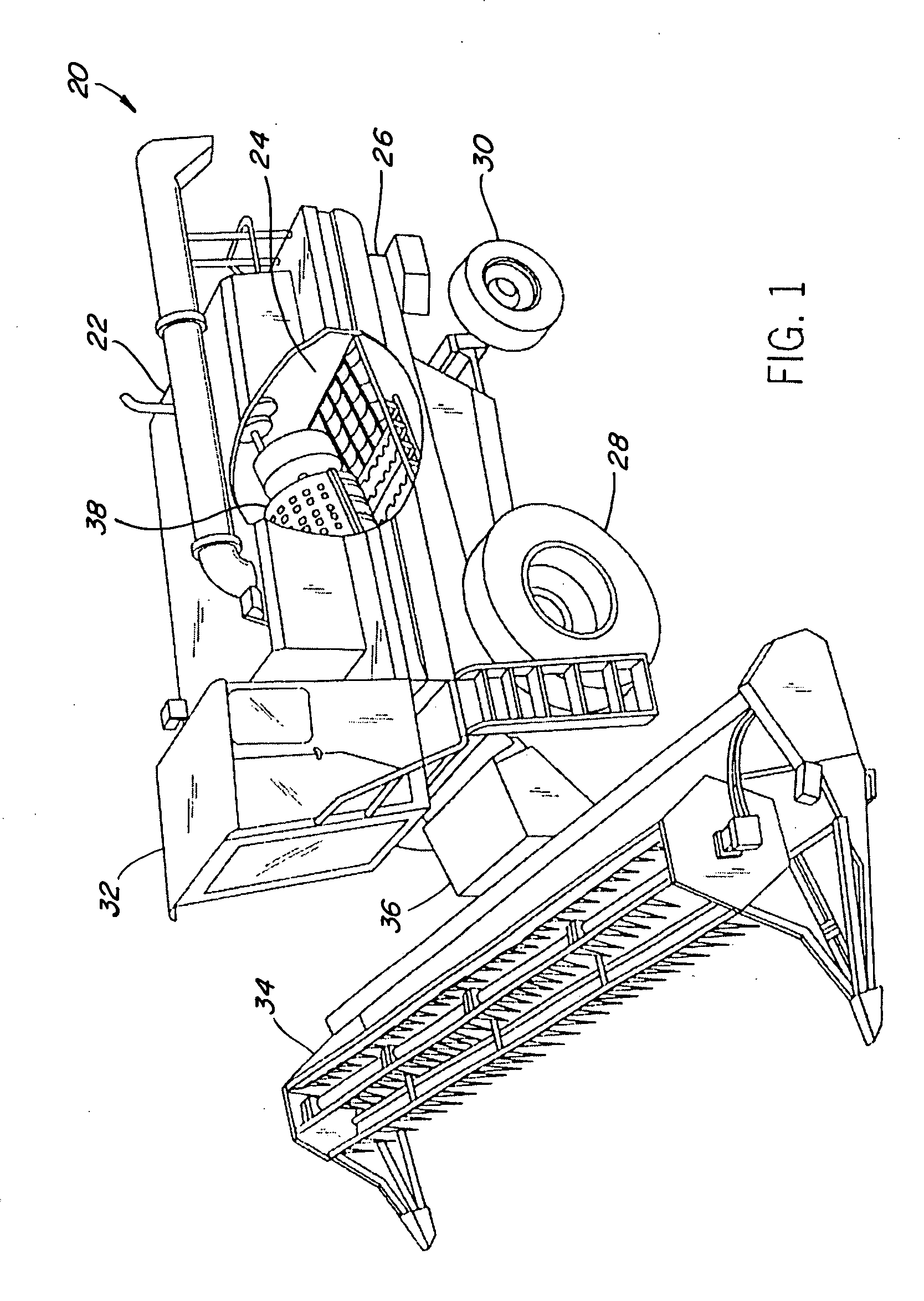
[0044] Referring to the drawings, FIG. 1 shows a self-propelled rotary combine 20 that includes a housing or body 22 defining an internal open area or space 24. While a conventional rotary combine is shown, it is anticipated that the present invention could be used with any type of combine, such as a conventional combine having a threshing cylinder and separation beaters (not shown) or a hybrid combine having a threshing cylinder and rotors (not shown). However, for ease of explanation, the present invention will be discussed hereinafter in conjunction with a self-propelled rotary combine 20 as illustrated by FIG. 1.

[0045] The body 22 of the combine 20, which can include a supporting frame 26, is supported on front drive wheels 28 and steerable rear wheels 30. The combine 20 is powered by an engine (not shown) and controlled from an operator's station 32.

[0046] A crop harvesting apparatus, otherwise referred to as a header 34, and an infeed mechanism 36 are attached at a forward e...


PUM


Abstract

A system and method for positively discharging crop residue from a combine for precisely and consistently delivering crop residue from the threshing and separating area of a combine to the combine's residue handling system or outwardly from the rear of the combine and onto the harvested field below as a windrow. The present invention can include, or operate in cooperation with, a discharge mechanism, such as a conventional discharge beater, which delivers at least some of the crop residue to a conveying mechanism of the system. The system also includes a guide mechanism including a door arrangement configurable in several alternative configurations for receiving and merging and regulating crop residue flow from the discharge mechanism and the conveying mechanism, and directing the merged flow to a desired processing mechanism, such as, but not limited to, a chaff spreader, a straw chopper and / or spreader, etc.

Description

[0001] This Patent Application claims priority from U.S. Provisional Patent Application Ser. No. 60 / 517,875, filed Nov. 7, 2003.TECHNICAL FIELD [0002] The present invention relates generally to a system and method for positively discharging crop residue from an agricultural combine, the system and method allowing for precise and consistent delivery of crop residue from the threshing and separating area of a combine to the residue handling system or outwardly from the rear of the combine in a windrowing configuration. BACKGROUND ART [0003] Agricultural combines are well known in the art for harvesting and threshing various agricultural crops, including for example, wheat, soybeans, corn, etc. Usually, agricultural combines include a harvesting apparatus, an infeed mechanism, a separating apparatus and a cleaning apparatus. In operation, the harvesting apparatus reaps the crop, which is planted in the ground. After reaping, the infeed mechanism feeds the crop to the separating apparat...

Claims


Application Information

Patent Timeline
IPC IPC(8): A01D41/12A01F12/40
CPCA01D41/1243
Inventor FARLEY, HERBERT M.LEHMAN, BARRY E.BRUMBACK, CLAY T.
Owner BLUE LEAF I P
Learn More