Device and method for the release of material for processing

a technology of material and release device, applied in the direction of liquid/fluent solid measurement, container, opening closed container, etc., can solve the problem of not enabling optimal use of bags and cartridges in the same device, and achieve the effect of effective emptying of bags

Inactive Publication Date: 2009-03-12
BUCK MANUEL
View PDF4 Cites 26 Cited by
  • Summary
  • Abstract
  • Description
  • Claims
  • Application Information

AI Technical Summary

Benefits of technology

[0017]It will be appreciated that a number of advantages will be provided by a piston that can be arranged for the working both of bags that are inserted into the cylinder and of cartridges which, featuring a cylinder in which the material to be processed is stored, can be inserted into the device. The design of the first side of the piston, which serves to bear upon the bag, ensures that the bags will, while being worked, not sustain damage and will empty optimally. The second side of the piston permits the actuation, with uniformly distributed pressing force, of a part that is borne so as to slide inside an inserted cartridge, thus obviating damage thereto.
[0018]It is of particular advantage if the piston feature a threaded bore that runs the integral length of thereof and along the longitudinal axis thereof, so that the piston, having either its first or second side oriented toward the guide rod, can be screwed onto the threaded bolt of the guide rod.
[0019]It is particularly advantageous, for the purpose of more effectively emptying the bag, that the first side of the piston have a shape that at least approximates that of the inner wall of a covering piece, which, being secured to the forward end of the cylinder by means of a first assembly ring, is transited by the expelled material to be processed. The outside of the piston, once having reached its terminal position, is brought up against the inner wall of the covering piece, so that only the empty casing of the bag remains interposed therebetween.
[0020]It is consequently proposed in this respect that the folded casing of the bag not hinder the progress of the piston as it moves toward its terminal position. The outside diameter of the piston is smaller than the inside diameter of the cylinder, an arrangement that allows for the creation of a lateral storage space for the folded bag casing between the piston and the inner wall of the cylinder.

Problems solved by technology

Due to the various demands made on the device, which become evident when bags or cartridges are being worked, the prior art devices have not enabled optimal employment of bags and cartridges in the same device.

Method used


Image

  • Device and method for the release of material for processing
  • Device and method for the release of material for processing
  • Device and method for the release of material for processing

Examples


Embodiment Construction

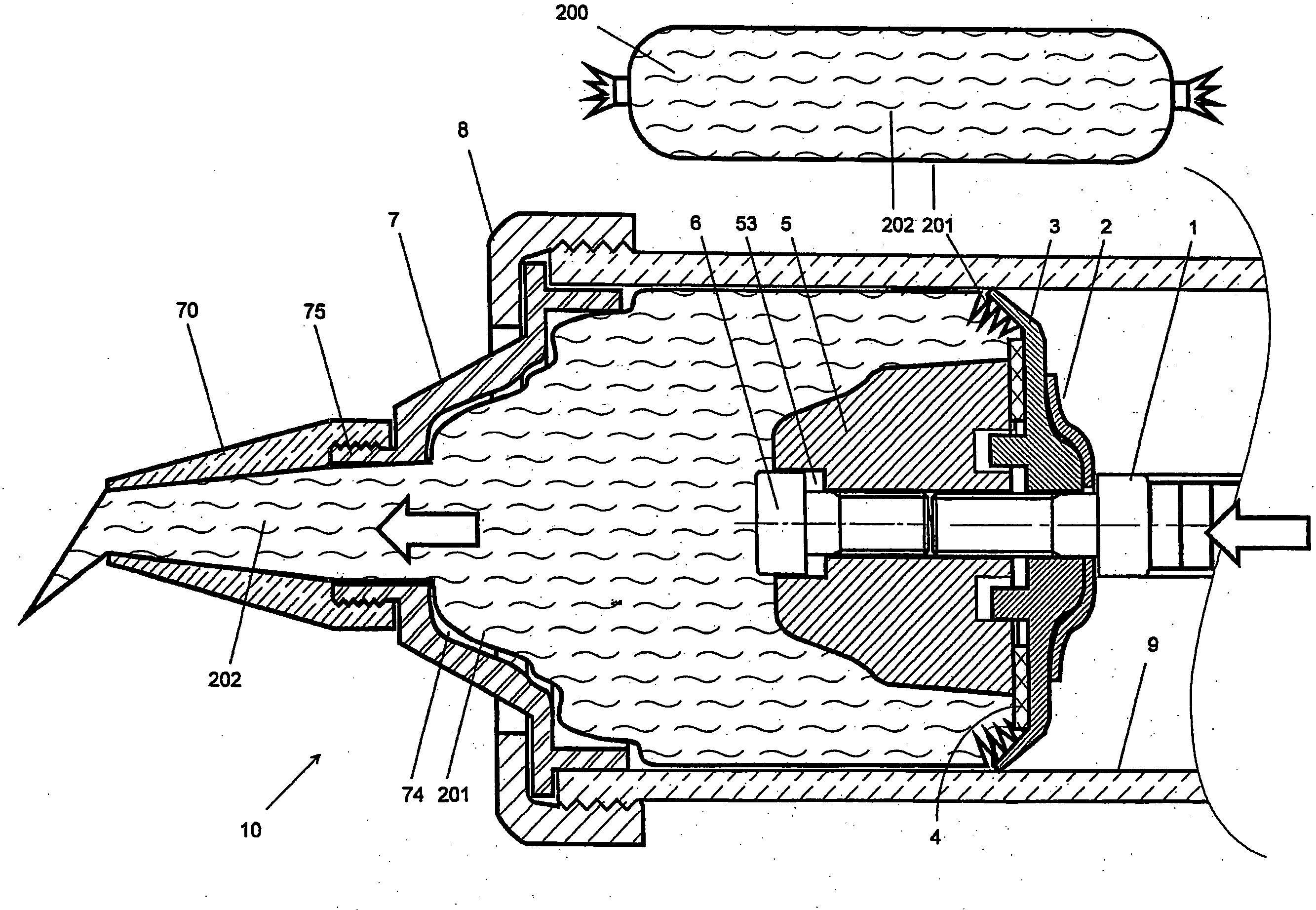
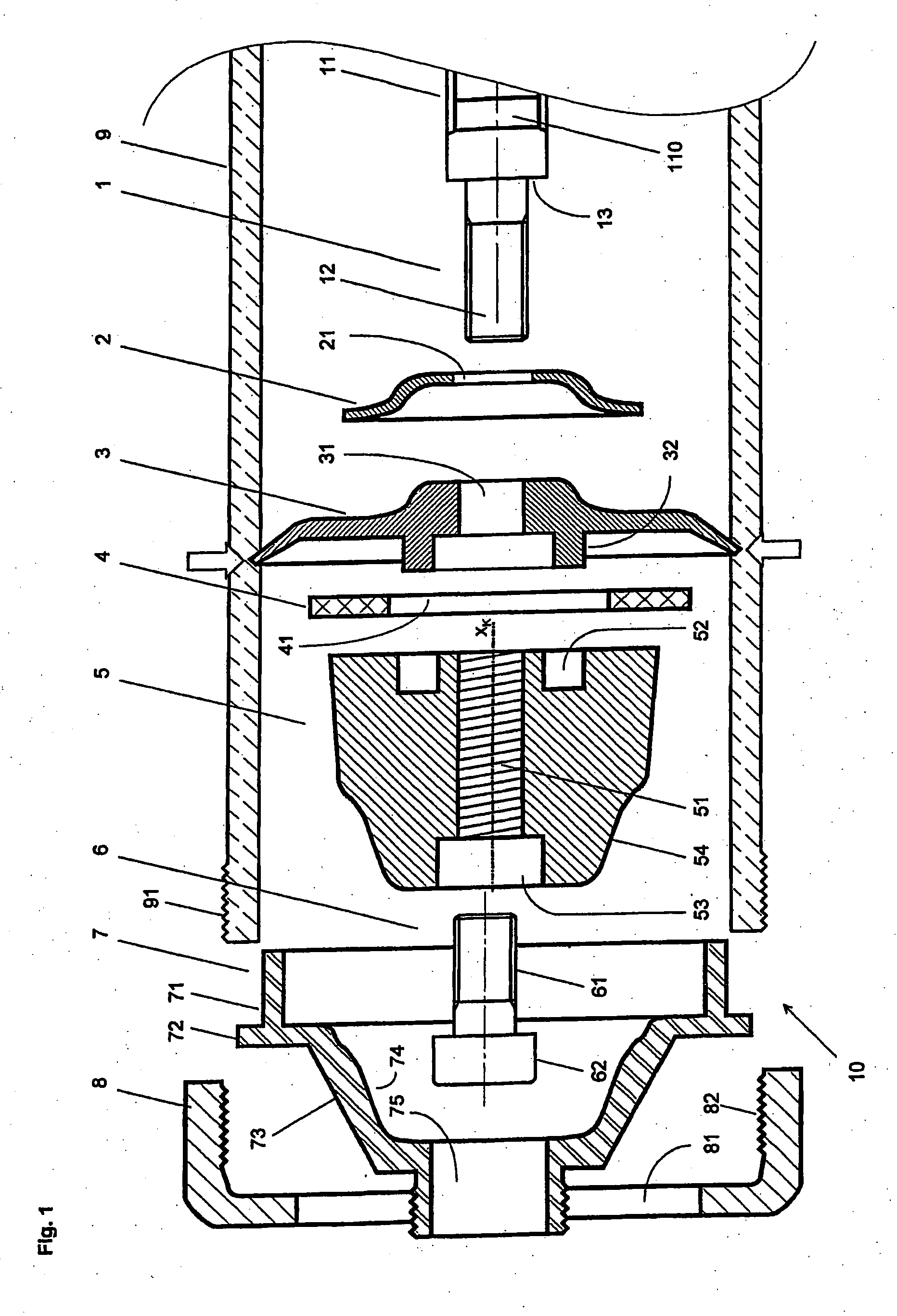
[0040]FIG. 1 shows an exploded view of not yet assembled parts 1, . . . , 9 of a preferred embodiment of device 10. Shown is a longitudinal section through a cylinder 9 which, being provided on both ends with an outer thread 91 (also see FIG. 7), can be connected frontally by means of a first assembly ring 8 to a covering piece 7. Capable of sliding axially inside cylinder 9 is a guide rod 1 which, being actuated by means of an actuation apparatus 800 (shown in FIG. 9), comprises a toothed rack 11 that is provided with a row of teeth 110 and a frontally-positioned terminal piece, which, in the manner of a screw, is provided with a threaded bolt 12 and a headpiece that forms a stop 13, such headpiece constituting part of toothed rack 11.

[0041]Also illustrated are a support element 2, a plate 3 and a sealing ring 4, each of which features a passage opening 21; 31 or 41 for the insertion of threaded bolt 12.

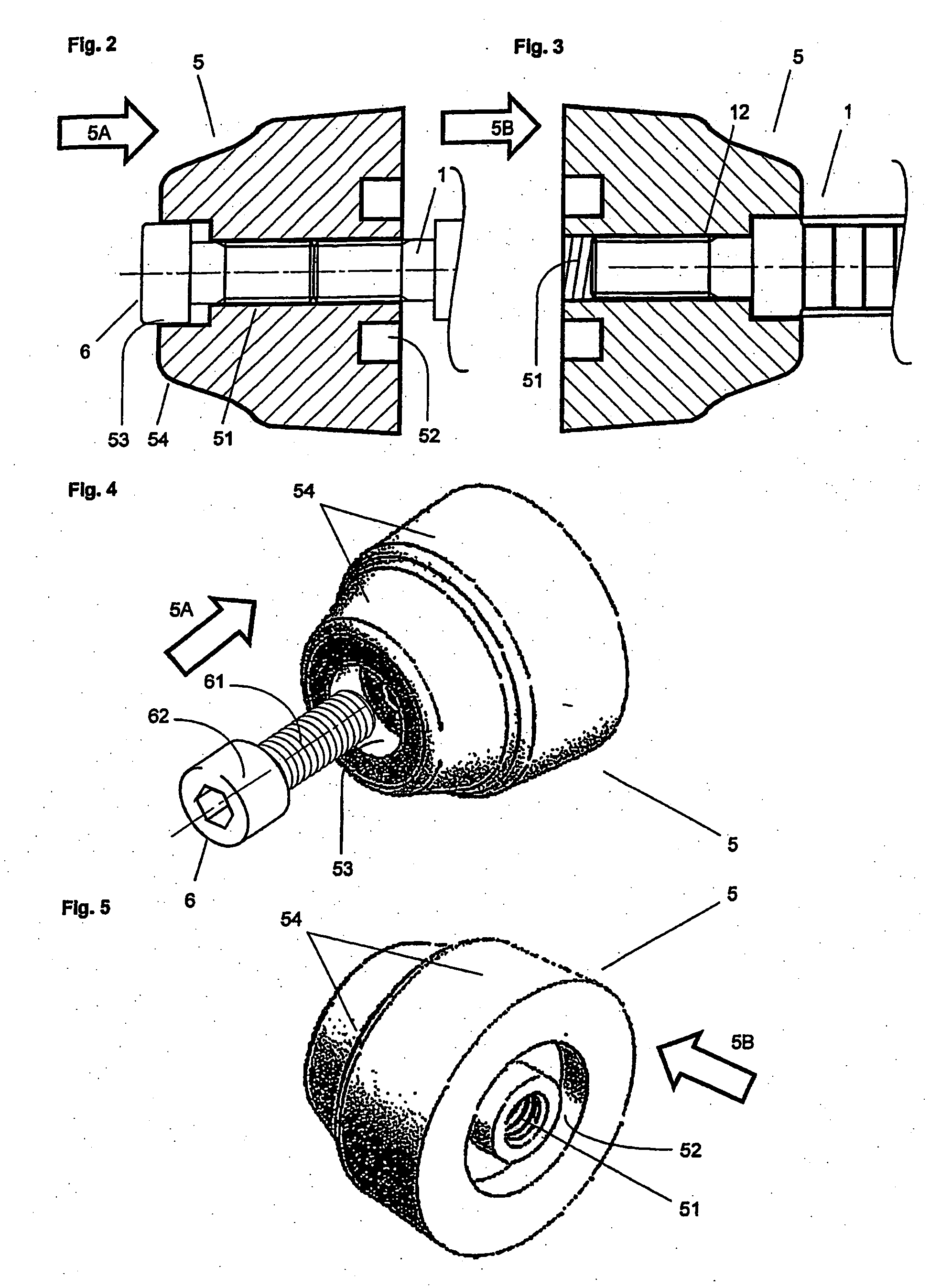
[0042]Also shown is a piston 5 that features a threaded bore 51, which, extendi...


PUM


Abstract

The device (10) for the release of material (202) for processing, comprises an actuator device (800), by means of which a guide rod (1), mounted for axial displacement, provided on the front thereof with a threaded pin (12) for connection to a piston (5), may be introduced into a cylinder (9; 309), such that the piston (5) acts on the material (202) for processing in the cylinder (9; 309) and forces the same from the cylinder (9; 309). According to the invention, the piston (5) comprises two opposing faces (5A, 5B), the first face (5A) of which acts on the material (202) for processing, housed in a bag (200), introduced into the cylinder (9) and the second face (5B) of which acts on material (202) for processing housed in the cylinder (309) in a cartridge (300) introduced into the device (10). The device (10) thus permits, after corresponding assembly of the piston (5), the processing of a bag introduced into the cylinder (9), or a cartridge (300) which may be inserted in the device (10).

Description

TECHNICAL DOMAIN[0001]The present invention is based on a device for the delivery of materials to be used, more particularly viscous or pasty materials such as sealants and agglutinants in accordance with the preamble of the first claim.[0002]The present invention relates furthermore to a method for delivering said materials to be used in accordance with the independent method claims.THE STATE OF THE ART[0003]Devices of this type, which are known by the names of injection pistol, Caulk Gun or Sealant Gun, and which have been disclosed, for example, in JP 11036571, JP 2003213926, JP 7041021, serve in the measured delivery of a sealant. Devices of this type are typically fitted with either a manual, an electric or a pneumatic actuation apparatus. Electrically-powered devices are manufactured, for example, by the MILWAUKEE ELECTRIC TOOL CORPORATION, e.g. production series 6560-2x.[0004]The device disclosed in JP 11036571 permits the delivery of sealant from a sausage-shaped bag that ca...

Claims


Application Information

Patent Timeline
Patent Type & Authority Applications(United States)
IPC IPC(8): B05C17/005B65D35/28B65D35/56G01F11/00
CPCB05C17/00576B05C17/00583G01F11/029B65D83/0011G01F11/026B05C17/01
Inventor BUCK, MANUEL
Owner BUCK MANUEL
Why Eureka
Try Eureka