
Maximum likelihood block decision feedback estimation for CCK demodulation apparatus and method

a decision-backward estimation and probability-based technology, applied in the field of demodulation of cck code symbols, can solve the problems of multipath reflection, bleeding, or spreading, of individual cck chips, and channel is more susceptible to bit errors

Active Publication Date: 2008-08-12
SILICON LAB INC
View PDF12 Cites 5 Cited by
  • Summary
  • Abstract
  • Description
  • Claims
  • Application Information

AI Technical Summary

Benefits of technology

[0022]3) a first subtractor which subtracts the effects of previous CCK symbols from the present symbol to generate a first subtractor output;
[0023]4) a pre-equalization register containing a value which includes the channel compensated effects of previous decision symbols for removing previous symbol contributions from the current symbol;
[0024]5) a demodulator having as inputs the first subtractor output, a phase φ2 derived from the iteration variable k, the four values of the post-equalization register associated with the phase φ2 derived from k which were expanded into 16 post-equalize values as described earlier, where the output of the first subtractor is applied to a simple FWT, the simple FWT performing an FWT on the first subtraction output using as a butterfly phase the φ2 which was derived fro

Problems solved by technology

At these higher data rates using CCK symbols, the channel is more susceptible to bit errors associated with the same multipath reflections, and greater care must be taken in the receiver signal processing leading up to demodulation of the symbols into decision data.
An additional degradation of the decision process comes in the form of multipath reflections.
Multipath reflections in the communications channel result in bleeding, or spreading, of individual CCK chips, and also generate delayed copies of the CCK chips.

Method used


Image

  • Maximum likelihood block decision feedback estimation for CCK demodulation apparatus and method
  • Maximum likelihood block decision feedback estimation for CCK demodulation apparatus and method
  • Maximum likelihood block decision feedback estimation for CCK demodulation apparatus and method

Examples


Embodiment Construction

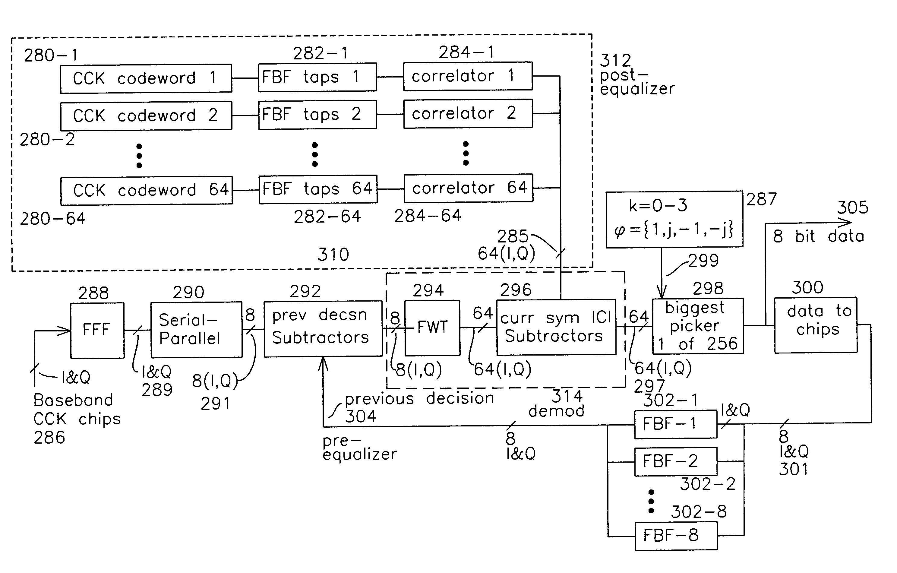
[0045]The approach as shown in FIG. 9 describes the advantages of using decision feedback equalization for removing inter-codeword ISI by estimating current symbol ICI and subtracting it to improve the decision on the current symbol. An implementation of the circuitry in FIG. 9 would entail a very extensive set of multipliers and adders. Each of the 64 feedback filters 282-1 through 282-64 would require approximately many adders and multipliers, and each of the correlators 284-1 through 284-64 would require many adders and multipliers. The 16 feedback filters 302-1 through 302-8 each require many adders and multipliers, and the current symbol subtractor 296 requires 64 simultaneous complex subtractions.

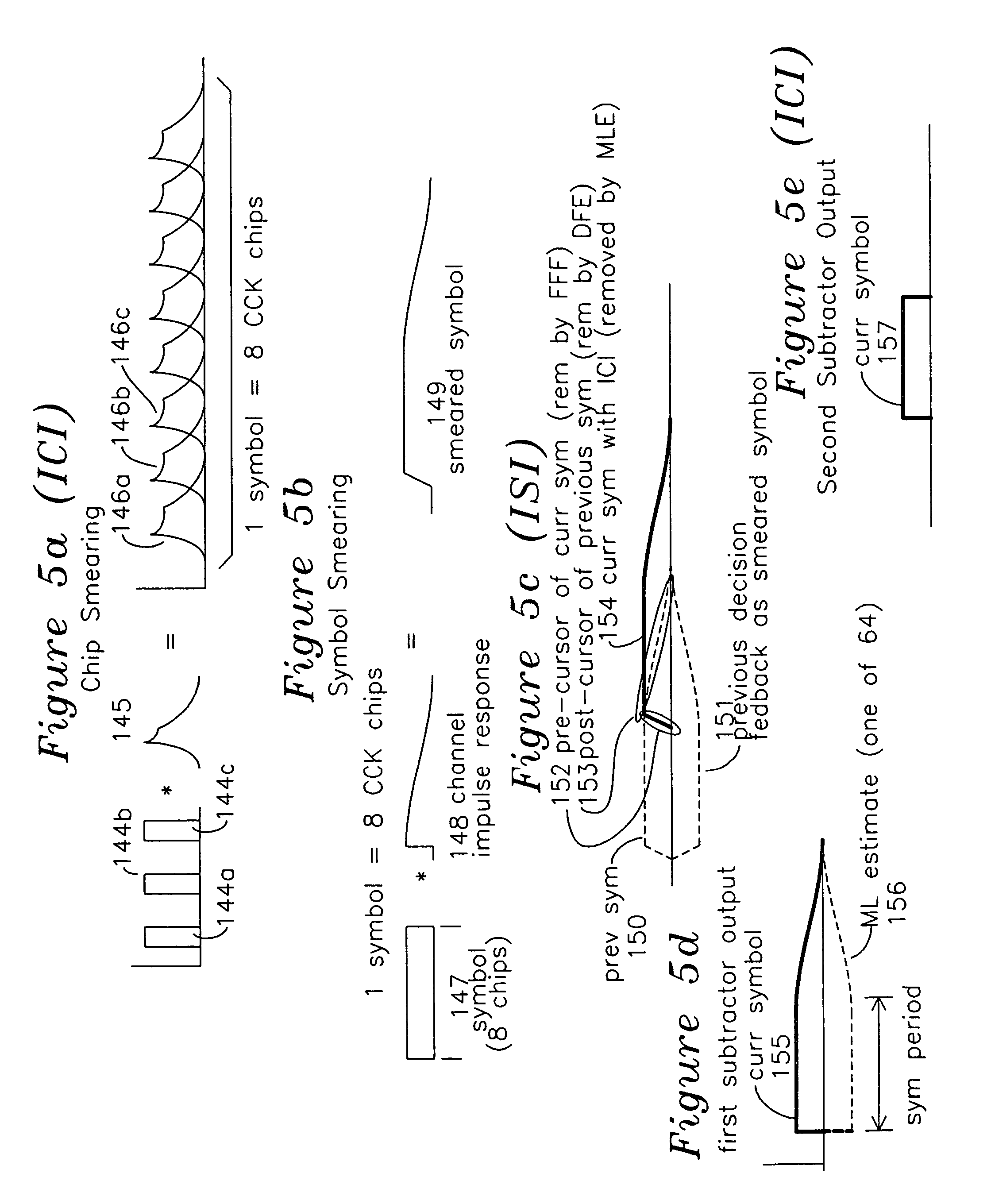
[0046]FIG. 11a shows the block diagram for a reduced complexity CCK demodulator including decision feedback equalization for pre-equalization as well as for post-equalization, and may be understood in combination with the operating waveforms of FIGS. 10a-10f. It is understood that the...


PUM


Abstract

A maximum likelihood CCK detector has a first subtractor which subtracts the contents of a pre-equalize register from a current symbol, and the output of this subtractor is coupled to a simple Fast Walsh Transform (FWT) with an iteration variable k. The output of the FWT is coupled to a second subtractor for subtracting a plurality of ICI corrections for all possible current symbols computed from the post-FWT domain value of the current CCK symbol and stored in post equalization registers. A post equalization register contains values computed from feedback filter coefficients determined during a packet preamble, where the feedback filter coefficients are provided to a reduced complexity post equalization value generator which populates the post equalization register using an iteration variable i.

Description

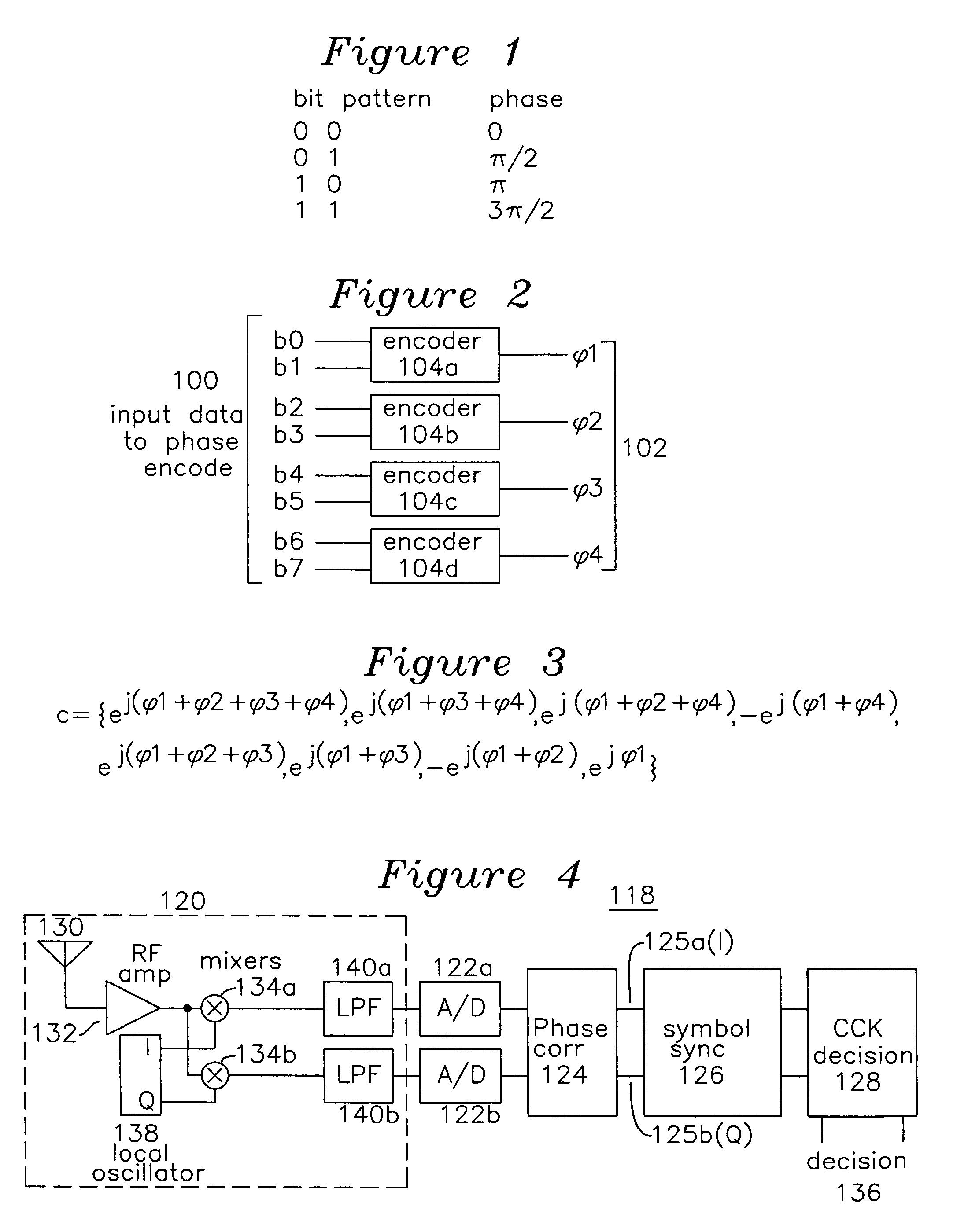
FIELD OF THE INVENTION[0001]The present invention is related to the demodulation of CCK code symbols, where each symbol is formed from a plurality of CCK chips in a wireless IEEE 802.11b system where these CCK code symbols are presently used for 5.5 Mb and 11 Mb data rates. The invention is extensible to demodulation of code symbols which are Direct Sequence Spread Spectrum (DSSS) phase encoded using Walsh-Hadamard chipping sequences.BACKGROUND OF THE INVENTION[0002]Prior art wireless communication systems are defined in the IEEE protocols for 802.11b. IEEE 802.11b is an example of a spread spectrum wireless protocol whereby a transmitter emits an isotropic or multidirectional signal including a sequence of broadband phase modulation of a carrier according to a known sequence, where the sequence is referred to as a chipping code. For 1 Mb and 2 Mb IEEE 802.11b data rates, the chipping code is a Barker code. A receiver may be placed within a reception distance from the source, and it...

Claims


Application Information

Patent Timeline
IPC IPC(8): H03H7/30H03H7/40H03K5/159
CPCH04B1/71057H04L25/03057H04L23/02
Inventor SAILAJA, SANKABATHULA DHARANI NAGAMURALI, PARTHASARATHYVENKATESH, NARASIMHAN
Owner SILICON LAB INC
Learn More