Device for measuring tibio-femoral force amplitudes and force locations in total knee arthroplasty

a technology of tibia-femoral force and probe, which is applied in the direction of diagnostic recording/measuring, instruments, gymnastics, etc., can solve the problems of inability to determine the application point of compressive force, relative large errors and repeatability problems, etc., and achieve the effect of facilitating the handling of the probe and improving the ergonomics of the prob

Active Publication Date: 2008-08-19
SYNTHES USA
View PDF9 Cites 113 Cited by
  • Summary
  • Abstract
  • Description
  • Claims
  • Application Information

AI Technical Summary

Benefits of technology

[0006]Advantages achieved by the invention are that the probe allows for measuring in real time the force amplitude and location separately for each condyle and therefore computing the moments acting on the knee joint to better assess the ligament balance; and keeping the patella at its anatomical place during the measurement, which is closer to the postoperative situation.
[0012]In a further embodiment, instead of electrically connecting the load sensitive sensors with the data processing instrument, (e.g. the computer) by means of cables, wireless telemetry may be used to transmit the measurement signals of the load sensors to the data processing instrument, e.g. the computer. This has the advantage of improving the ergonomics of the probe, and the handling of the probe may be facilitated as well.

Problems solved by technology

Assessing the ligament forces and moments acting in the knee “by hand” is subjective, and can lead to relatively large errors and repeatability problems.
A disadvantage of this probe is that it is not possible to determine the point of application of the compressive force.

Method used


Image

  • Device for measuring tibio-femoral force amplitudes and force locations in total knee arthroplasty
  • Device for measuring tibio-femoral force amplitudes and force locations in total knee arthroplasty
  • Device for measuring tibio-femoral force amplitudes and force locations in total knee arthroplasty

Examples


Embodiment Construction

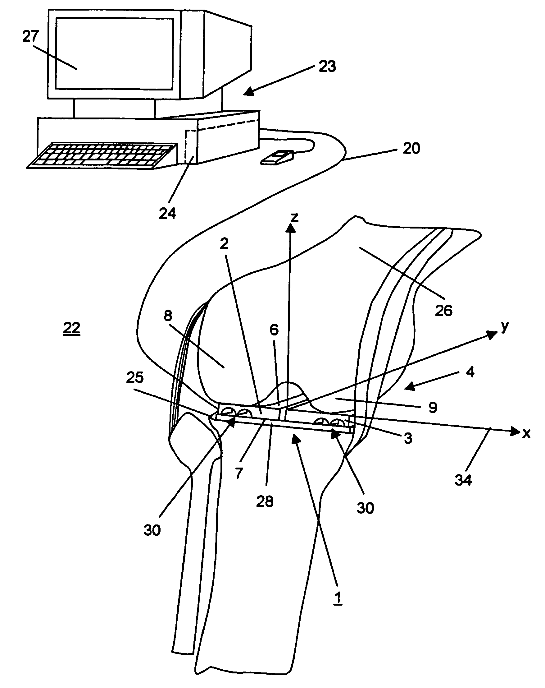
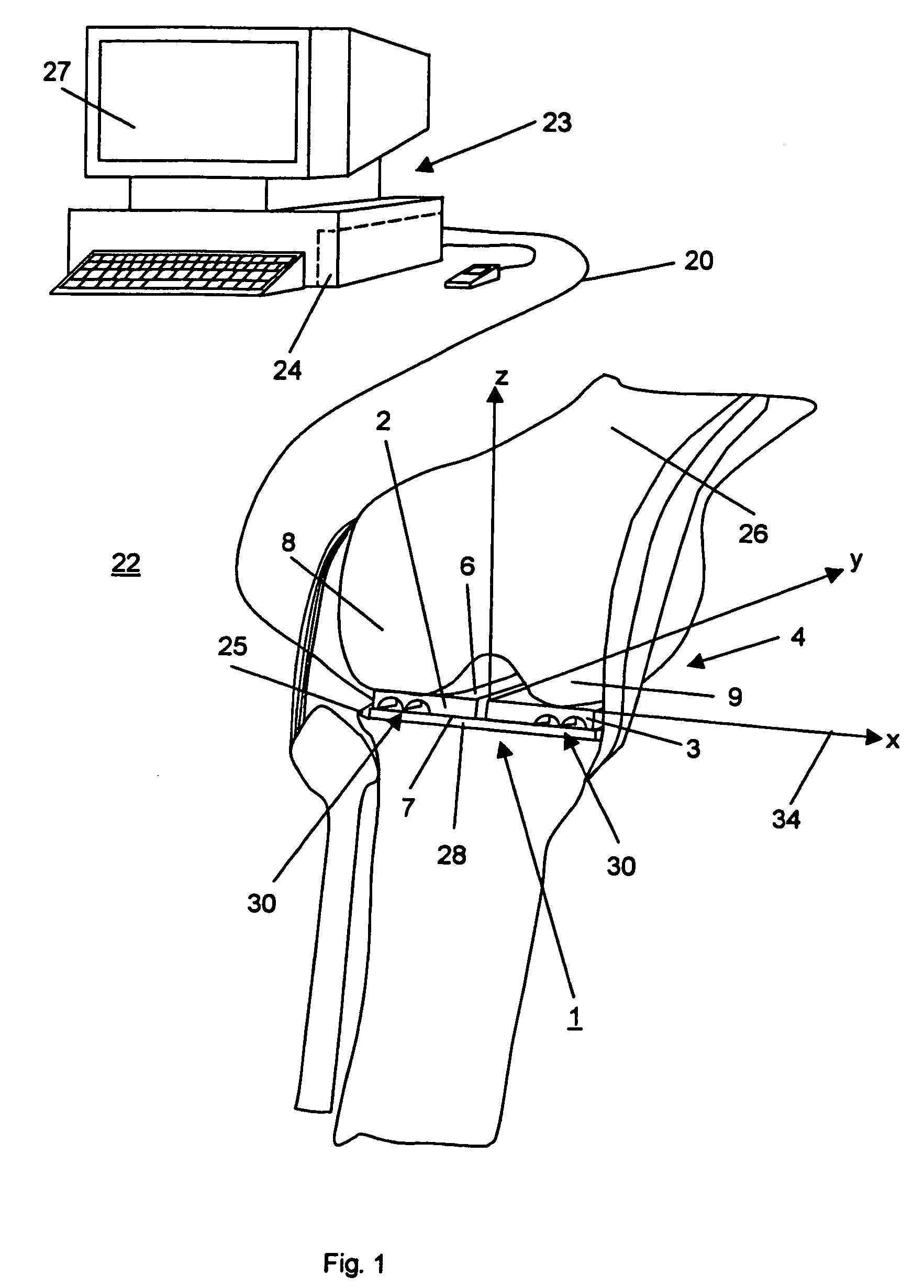
[0016]FIG. 1 represents a measuring apparatus 22 comprising a probe 1 situated between the tibial plateau 25 and the two condyles 8, 9 of a human knee joint 4. The measuring apparatus 22 may also comprise a data acquisition and processing instrument 24 connected wirelessly or by means of cables 20 to the probe 1 and a computer 23. The probe 1 may comprise two load sensitive plates 2, 3, each having a top surface 6 and a bottom surface 7. The bottom surfaces 7 may be in contact with the top surface of a tibial base plate 28 lying on the tibial plateau 25 and each of the top surfaces 6 may be in contact with one condyle 8, 9 of the femur 26. Each load sensitive plate 2, 3 is situated in one knee-compartment and is subjected to the forces of each condyle 8, 9. The probe may further comprise a set of wedges allowing a variation of the tibio-femoral gap according to the patient anatomy and ligament releasing procedure.

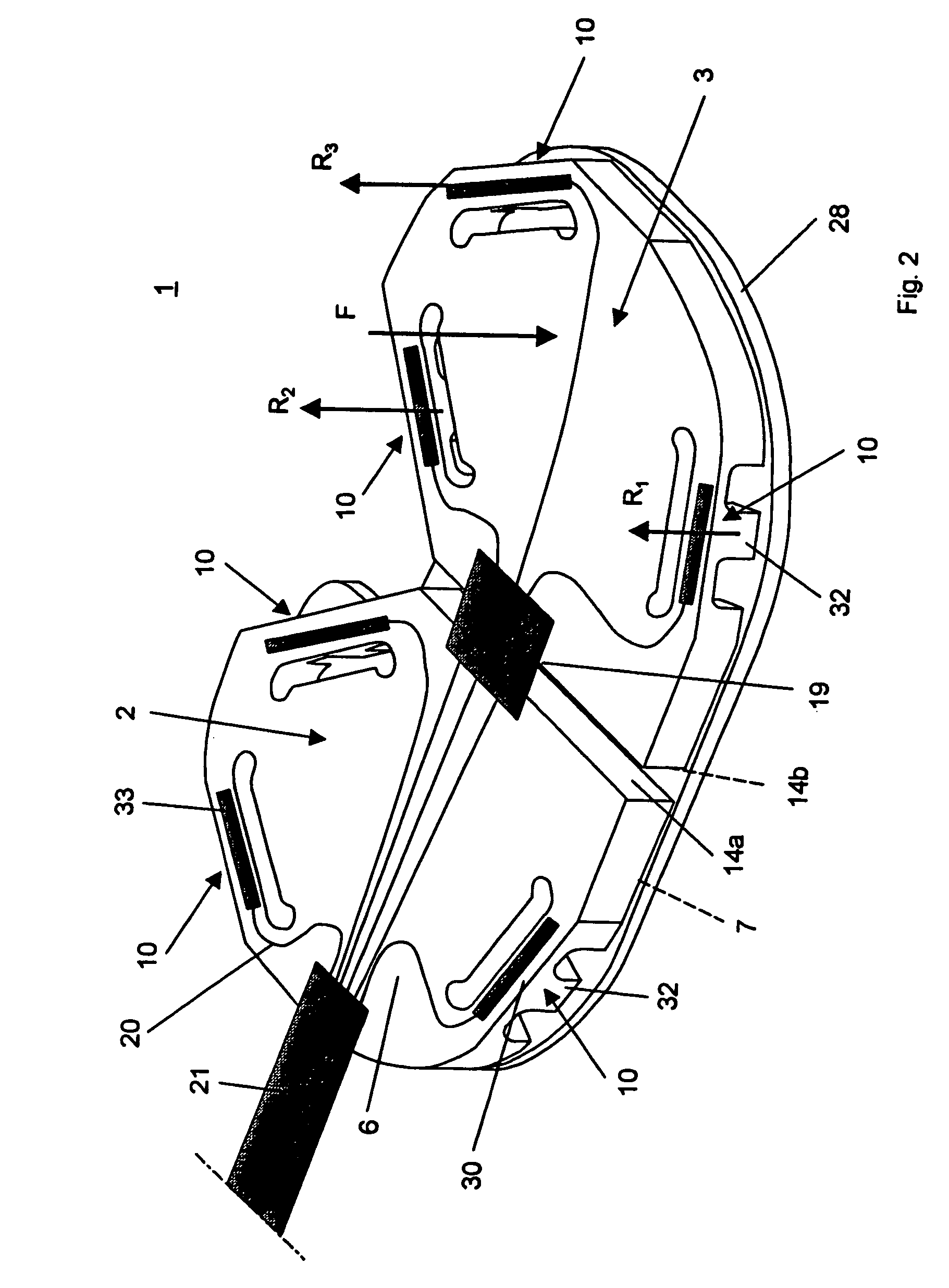
[0017]FIG. 2 depicts a perspective view on an exemplary embodiment of ...


PUM

PropertyMeasurementUnit
distanceaaaaaaaaaa
force amplitudesaaaaaaaaaa
flexibleaaaaaaaaaa

Abstract

A probe used during a total knee arthroplasty for measuring forces and locations of their points of application and thereby moments includes two load sensitive plates t to be inserted in one joint-compartment of a knee joint each and each being provided with a top surface and a bottom surface. At least two load sensors may be situated on the top surfaces and / or the bottom surface of each load sensitive plate.

Description

CROSS REFERENCE TO RELATED APPLICATION[0001]This application is a continuation of International Patent Application No. PCT / CH2004 / 000361, filed Jun. 15, 2004, the entire contents of which is expressly incorporated herein by reference.TECHNICAL FIELD[0002]The present invention relates to a probe for measuring force amplitudes, locations and moments of force.BACKGROUND OF THE INVENTION[0003]During a Total Knee Arthroplasty (TKA), a surgeon needs to balance the collateral knee joint ligaments in order to ensure a stable artificial joint. Conventionally, the balance assessment is based on the surgeon's perception and experience by manually manipulating the knee joint. Assessing the ligament forces and moments acting in the knee “by hand” is subjective, and can lead to relatively large errors and repeatability problems.[0004]In European document EP 1 304 093 by GOUGEON, a probe is used which allows the measurement of the compressive forces between each condyle of the femur and the tibial...

Claims


Application Information

Patent Timeline
Patent Type & Authority Patents(United States)
IPC IPC(8): G01B5/30A61B5/22A61F2/46G01L1/22
CPCA61B5/224A61B5/4528A61B19/46A61B2019/464A61B5/4533A61B90/06A61B2090/064
Inventor CROTTET, DENISPAPPAS, ION PETROSMAEDER, THOMASJACQ, CAROLINEBLEULER, HANNES
Owner SYNTHES USA
Why Eureka
Try Eureka