MEMS-based monitoring

a monitoring device and monitoring device technology, applied in the direction of fluid pressure measurement by mechanical elements, vibration measurement in solids, electrical/magnetic measurement arrangements, etc., can solve the problems of reducing the operating affecting the operation efficiency of the machine, and adding mass and size to the componen

Active Publication Date: 2008-08-19
INT ELECTRONICS MACHINES
View PDF19 Cites 41 Cited by
  • Summary
  • Abstract
  • Description
  • Claims
  • Application Information

AI Technical Summary

Problems solved by technology

Such repeated stress / strain eventually causes a component to fail.
However, this approach frequently requires a massive over design of the component, thereby adding mass and size to the component, which reduces the operating efficiency of the machine.
As a result, use of this approach is often limited to applications in which the component is extremely expensive to replace, the component absolutely cannot fail, and there is sufficient space and weight available in the machine to accommodate the over designed component.
Typically, this approach is limited to components that are relatively inexpensive to replace.
However, this approach is limited to machines having a sufficiently long operating history.
Additionally, since the approach is statistical, unexpected failure is possible.
As a result, a worst-case scenario may be assumed in practical applications, which can result in a component being disposed long before its useful lifetime would have ended.
However, since this approach is also statistical, large safety margins are frequently used, which can result in a component being disposed long before its useful lifetime would have ended.
However, to date, many components have not been effectively instrumented for monitoring due to size constraints and / or operating conditions (e.g., extreme heat, cold, vibration, and / or the like).
Additionally, the monitoring instruments frequently require wiring for communication and / or power, which often cannot be included in moving components.
The limiting component is a component whose operational parameters limits the use of one or more additional components, and therefore limits the performance of the machine.
In particular, a maximum amount of stress / strain that a component can withstand may be limited due to space / weight / material constraints of the component.
In this case, since the actual stress / strain cannot be measured, operation of the other component(s) will be limited to keep the stress / strain induced on the component within safe limits based on the model (and some safety margin).

Method used


Image

  • MEMS-based monitoring
  • MEMS-based monitoring
  • MEMS-based monitoring

Examples


Embodiment Construction

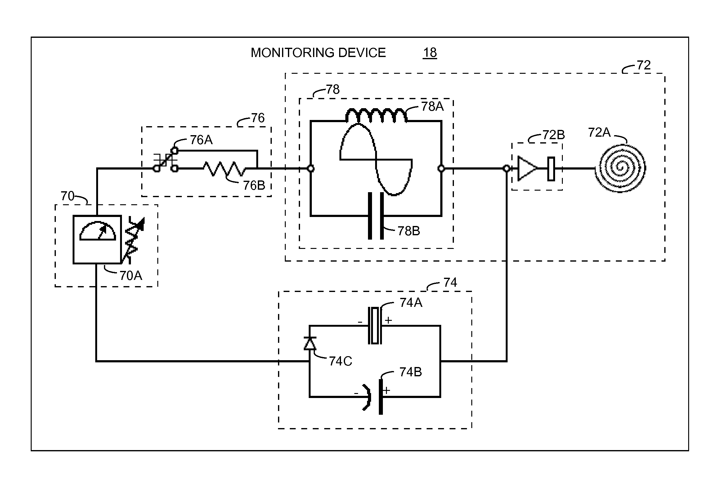
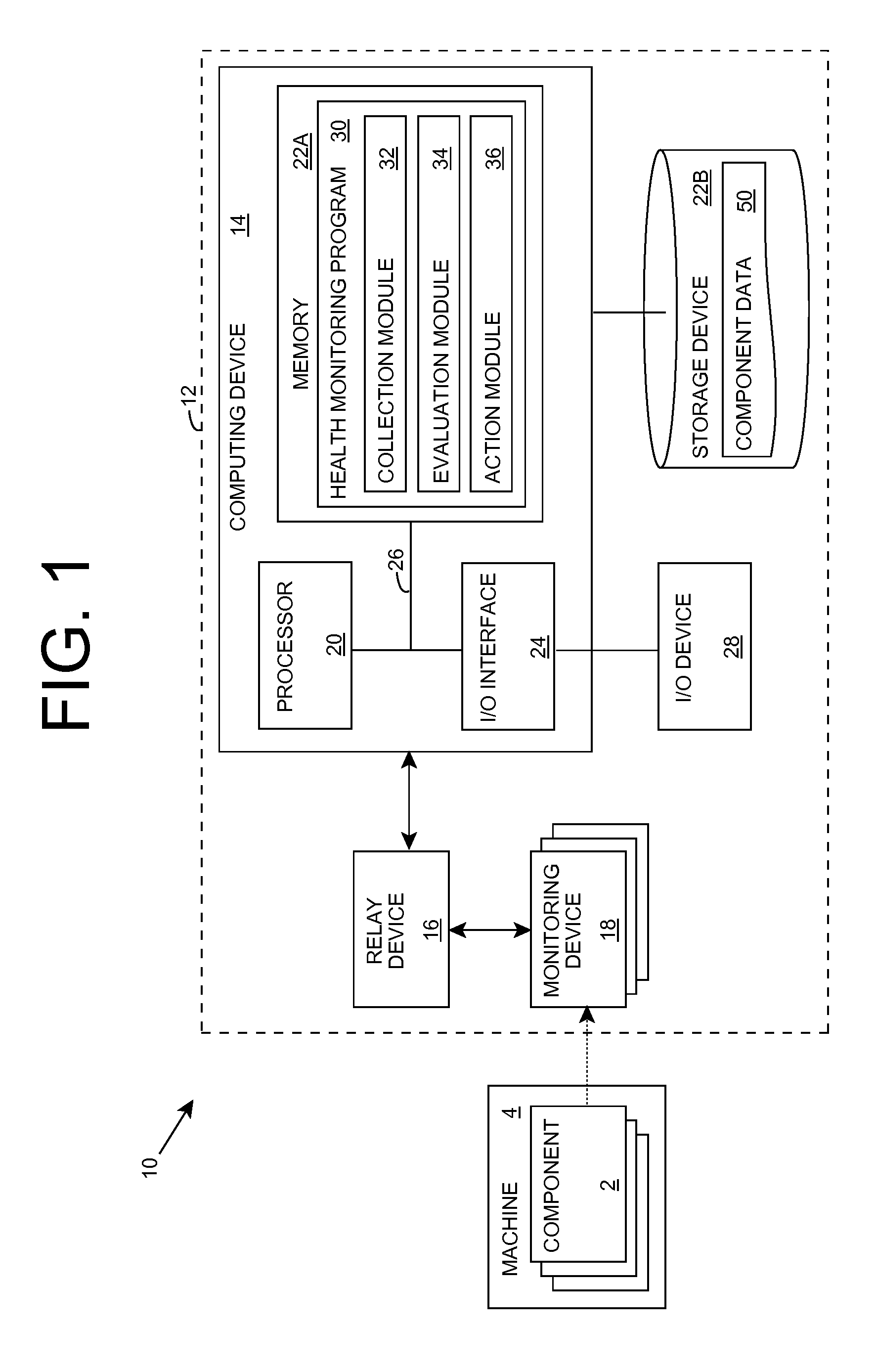
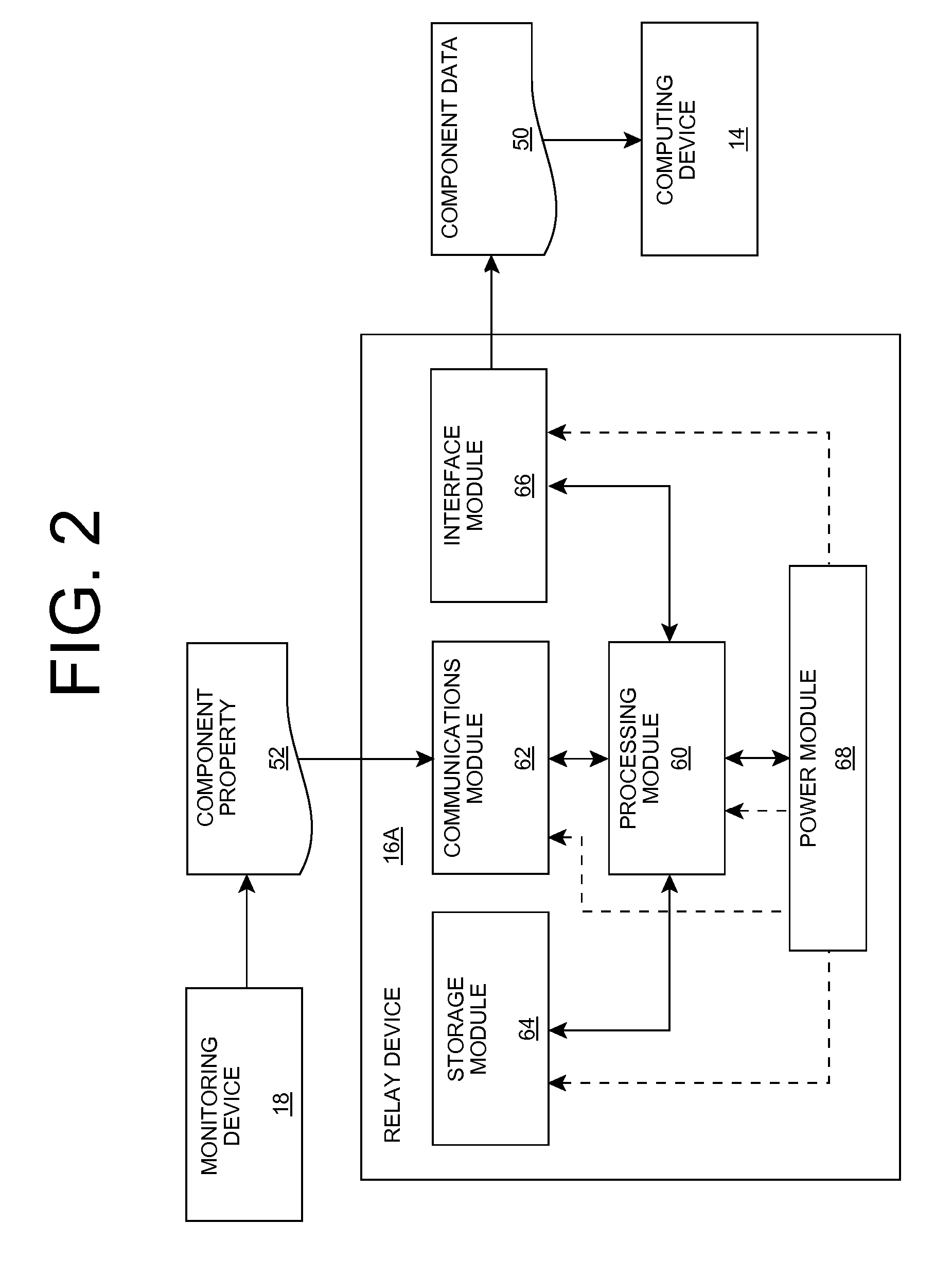
[0033]As indicated above, aspects of the invention provide a solution for monitoring a property of an object and / or an area using a Micro-ElectroMechanical Systems (MEMS)-based monitoring device. In an embodiment of the invention, the MEMS-based monitoring device includes a MEMS-based sensing device for obtaining data based on a property of the object and / or area and a power generation device that generates power from an ambient condition of the monitoring device. In this manner, the monitoring device can operate independent of any outside power sources or other devices. Further, the monitoring device can include a transmitter that transmits a signal based on the property. The monitoring device can be used to monitor a moving component of a machine, and can be integrated with a health monitoring system of the machine using one or more relay devices. As used herein, unless otherwise noted, the term “set” means one or more (i.e., at least one) and the phrase “any solution” means any n...


PUM


Abstract

A solution for monitoring a property of an object and / or an area using a Micro-ElectroMechanical Systems (MEMS)-based monitoring device is provided. In an embodiment of the invention, the MEMS-based monitoring device includes a MEMS-based sensing device for obtaining data based on a property of the object and / or area and a power generation device that generates power from an ambient condition of the monitoring device. In this manner, the monitoring device can operate independent of any outside power sources or other devices. Further, the monitoring device can include a transmitter that transmits a signal based on the property. The monitoring device can be used to monitor a moving component of a machine, and can be integrated with a health monitoring system of the machine using one or more relay devices.

Description

REFERENCE TO RELATED APPLICATION[0001]The current application claims the benefit of co-pending U.S. Provisional Application No. 60 / 717,266, filed on 16 Sep. 2005, which is hereby incorporated herein by reference.FIELD OF THE INVENTION[0002]Aspects of the invention relate generally to monitoring physical parameters, and more particularly, to a solution for monitoring properties of a component and / or an area.BACKGROUND OF THE INVENTION[0003]Complex machinery, such as vehicles (e.g., an automobile, plane, rotorcraft, locomotive, etc.), generators, automated machining tools, etc., include numerous constituent components (e.g., levers, arms, pistons, driveshafts, clutch plates, etc.) that move and are subject to stress and strain during their operating lifetime. Such repeated stress / strain eventually causes a component to fail. To avoid failure during operation of the machinery, numerous approaches can be used.[0004]For example, the component can be manufactured to a sufficient robustnes...

Claims


Application Information

Patent Timeline
Patent Type & Authority Patents(United States)
IPC IPC(8): G01M10/00G01H1/00
CPCG07C3/00
Inventor MIAN, ZAHID F.SPOOR, RYK E.
Owner INT ELECTRONICS MACHINES
Why Eureka
Try Eureka