Apparatus and method for maintaining control of a drilling machine

a technology for maintaining control and drilling machines, applied in the direction of drilling pipes, enzymology, borehole/well accessories, etc., can solve the problems of difficult maintenance of these operational levels difficult to maintain these operational levels for an operator to maintain for a long time, and difficult to maintain the control devi

Inactive Publication Date: 2008-08-19
CHARLES MACHINE WORKS
View PDF34 Cites 14 Cited by
  • Summary
  • Abstract
  • Description
  • Claims
  • Application Information

AI Technical Summary

Benefits of technology

[0008]The present invention comprises an apparatu

Problems solved by technology

The operator then must try and maintain these operational levels by holding the joystick or lever in the desired position, often for long periods of time.
Additionally, because of human fatigue and uncertainty of actual operational levels, it proves very difficult for an operator to maintain these operational levels f

Method used


Image

  • Apparatus and method for maintaining control of a drilling machine
  • Apparatus and method for maintaining control of a drilling machine
  • Apparatus and method for maintaining control of a drilling machine

Examples


Embodiment Construction

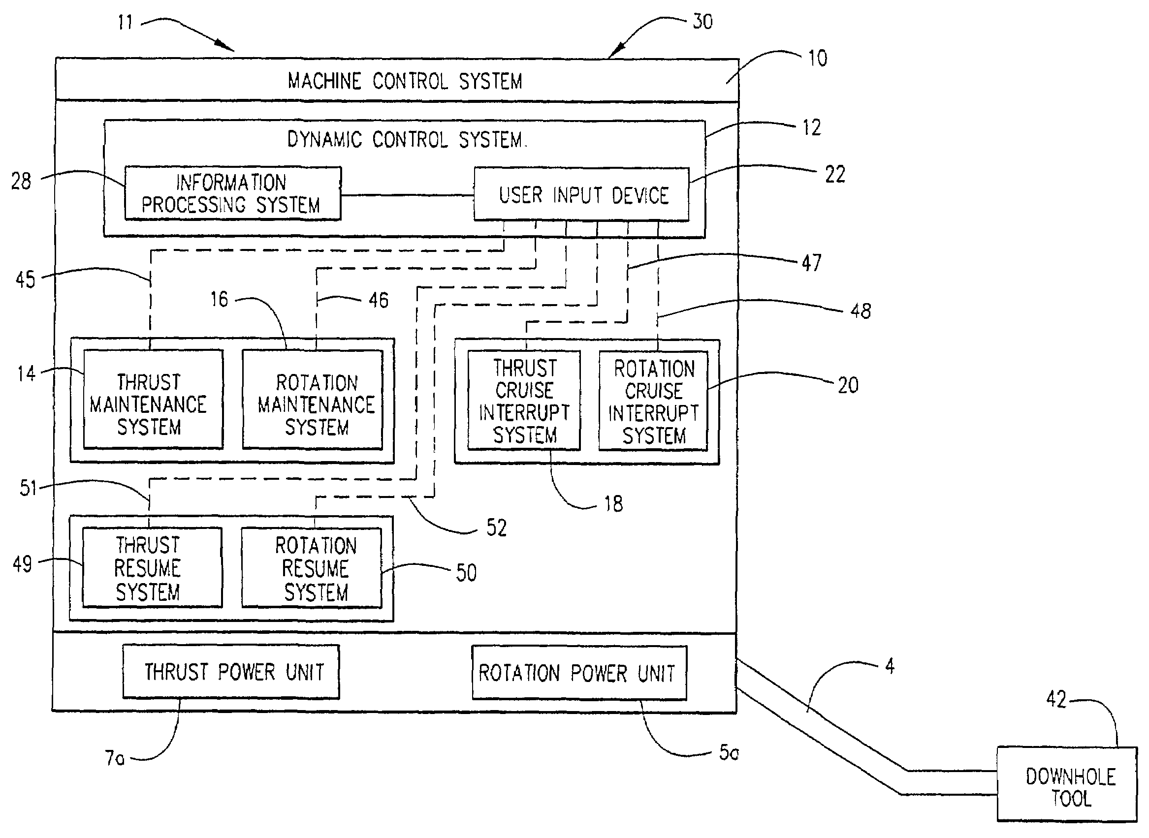
[0026]Generally, the present invention provides a system for maintaining control of a machine which generates varying outputs of thrust and rotation in response to control signals, typically thrust input signals or rotation input signals. The system has two distinct portions, namely, the operator input portion and the control and output portion. The operator input portion consists of primary thrust and rotation control and the adjustment control. Through these controls, the operator can enter the desired operational conditions and levels for rotation and thrust on a machine either singly or in combination. The control and output portion on the other hand, consists of a controller and proportional control valves for the thrust and rotation power units. The control system interprets all the desired operational conditions from the input portion and sends commands to the respective control valves of the power units to produce the desired outputs. However, it may be noted that the desire...


PUM

PropertyMeasurementUnit
Pressureaaaaaaaaaa
Lengthaaaaaaaaaa
Subsurfaceaaaaaaaaaa

Abstract

An apparatus is provided for maintaining control of a machine which produces thrust, rotation or other outputs in response to input signals. The apparatus has two distinct parts, namely the operator input portion and the output portion. The operator input portion consists of the primary thrust, rotation and other output control, and the input signal generation, signal maintenance and signal resume control. Through these controls, the operator enters the desired operation at conditions and levels for rotation, thrust, and other input signals. The output portion consists of an information processing and control portion and the power units for rotation, thrust and other outputs generated from the machine. The information processing and control system interprets all of the desired operational conditions and levels from the input portion and sends commands to the thrust, rotation and other power units to produce the desired outputs in response to the input signals.

Description

CROSS REFERENCE TO RELATED APPLICATION[0001]This application claims the benefit of U.S. Provisional Application No. 60 / 219,091, filed on Jul. 18, 2000, the contents of which are incorporated herein fully by reference.FIELD OF THE INVENTION[0002]The present invention relates to the field of horizontal directional drilling, and more particularly but not by way of limitation, to a control apparatus and associated method for maintaining control of the thrust or pullback, together with rotation of a horizontal directional drilling machine acting on a drill string to form a subterranean bore hole.BACKGROUND OF THE INVENTION[0003]Horizontal directional drilling machines are used to install underground utilities or other objects. This technology is gaining widespread favor because it minimizes ground surface disruption and the likelihood of damaging already-buried objects.[0004]Horizontal directional drilling operations generally consist of using the drilling machine to advance a drill stri...

Claims


Application Information

Patent Timeline
IPC IPC(8): E21B7/04A61K38/00C12N9/00E21B44/00E21B44/02
CPCC12N9/93B60K37/02E21B44/00E21B44/02E21B7/046A61K38/00
Inventor KOCH, GEOFF D.WIDENER, LEEPAYNE, DAVID R.
Owner CHARLES MACHINE WORKS
Why Eureka
Try Eureka