
Method for adjusting voltage on a powered Faraday shield

a faraday shield and voltage adjustment technology, applied in the field of semiconductor fabrication, can solve the problems of non-uniform deposition and/or non-uniform sputtering, interference with the etching process, drifting into the etching process, etc., to prevent and mitigate the deposition of non-volatile reaction products, and easy to adjust the voltage

Inactive Publication Date: 2008-08-19
LAM RES CORP
View PDF1 Cites 14 Cited by
  • Summary
  • Abstract
  • Description
  • Claims
  • Application Information

AI Technical Summary

Benefits of technology

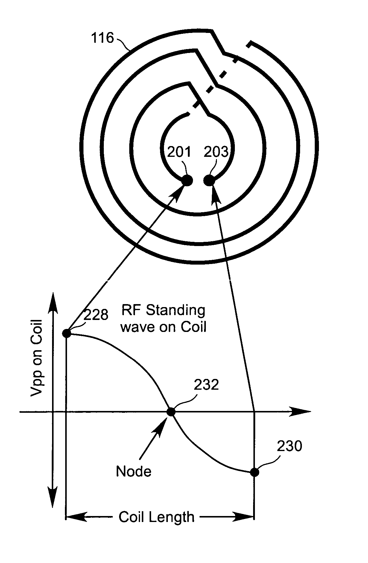
The present invention provides an apparatus and method to easily adjust the voltage on a Faraday shield of an inductively coupled plasma etching apparatus. This helps to control plasma sputtering against a chamber window to prevent and mitigate non-volatile reaction products. The invention can be implemented in various ways, such as a process, an apparatus, a system, a device, or a method. The technical effect of the invention is to provide better control and prevention of non-volatile reaction products deposition on the chamber window, which can improve the efficiency and reliability of the plasma etching process.

Problems solved by technology

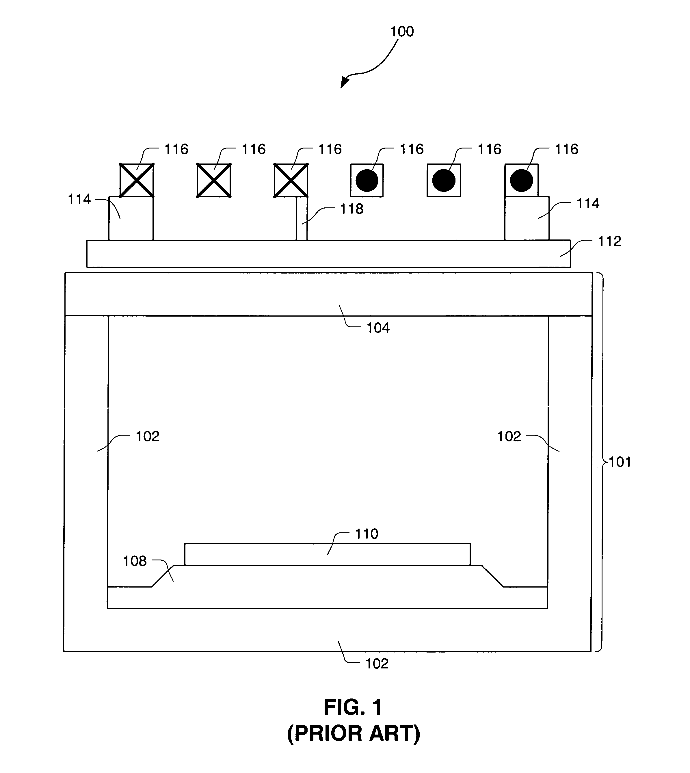
Adherence of non-volatile reaction products to the chamber window 104 may interfere with the etching process.
Additionally, excessive deposition may result in particles flaking off the chamber window 104 onto the wafer 110, thus interfering with the etching process.
Non-uniform deposition and / or non-uniform sputter can introduce drift into the etching process.
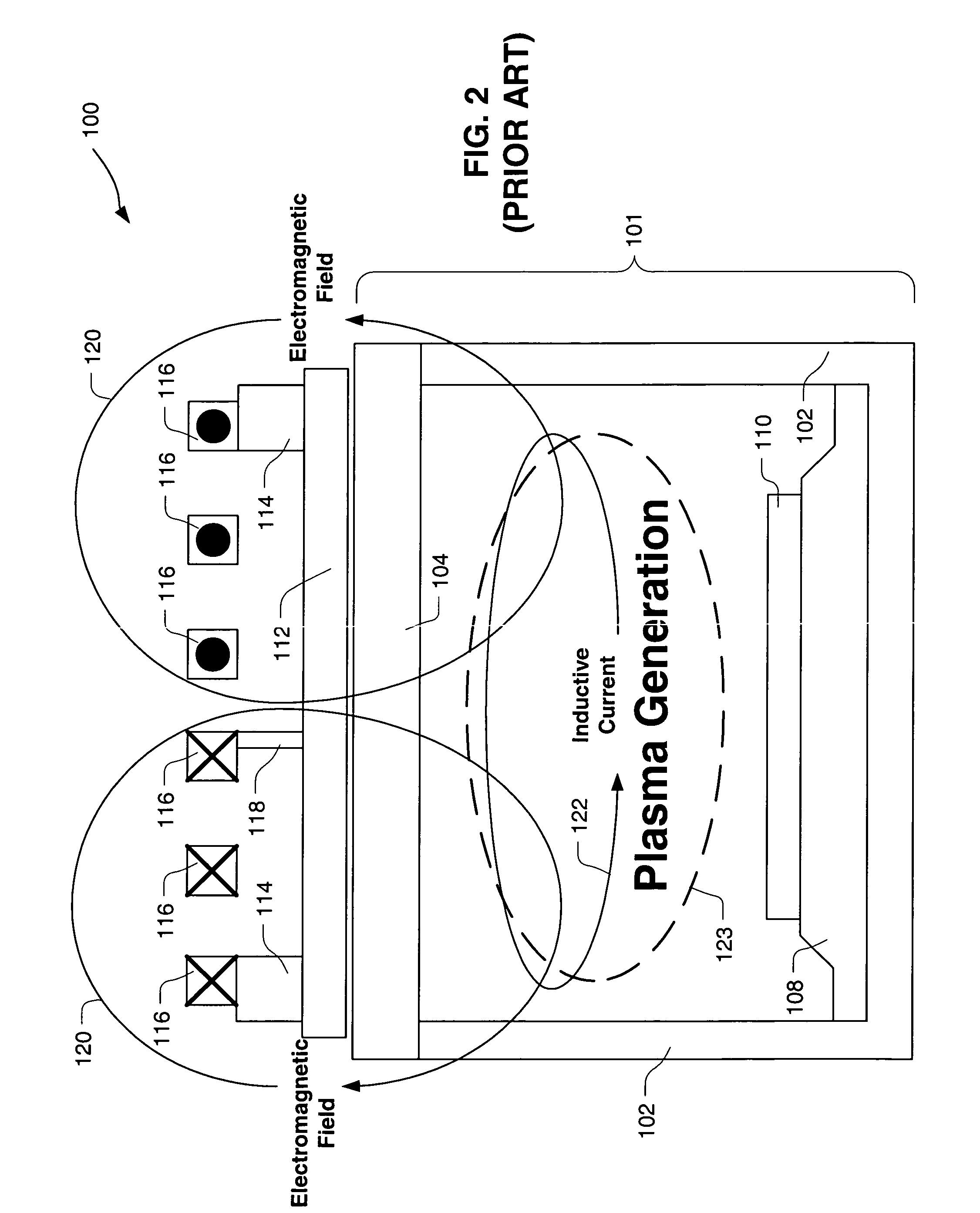
However, even uniform deposition of non-volatile reaction products on the chamber window 104 will continue to interfere with the etching process as previously discussed.
With too high a voltage, incident ions 132 will be directed toward the chamber window 104 having too much energy and too much intensity, thus causing too much sputtering.
The presence of unwanted species in the etching process environment is particularly undesirable because it leads to poor reproducibility of the etching process conditions.
Consequently, a certain setting for the appropriate Faraday shield voltage for a given etch step may not be optimal in other etch steps.
Such mechanical reconfiguration has a narrow operating window and is costly in terms of material expense and time resulting in lower wafer throughput.

Method used


Image

  • Method for adjusting voltage on a powered Faraday shield
  • Method for adjusting voltage on a powered Faraday shield
  • Method for adjusting voltage on a powered Faraday shield

Examples


Embodiment Construction

[0036]An invention is disclosed for an apparatus and method for adjusting the voltage applied to a Faraday shield of an inductively coupled plasma etching apparatus. Broadly speaking, the present invention allows an appropriate voltage to be easily and variably applied to a Faraday shield such that sputtering of a plasma can be controlled to prevent and mitigate deposition of non-volatile reaction products that adversely affect an etching process. The appropriate voltage for a particular etching process or step can be applied to the Faraday shield by simply adjusting a tuning capacitor. Thus, the present invention eliminates the need to mechanically reconfigure the etching apparatus to obtain an appropriate Faraday shield voltage for a particular etching process or step.

[0037]In the following description, numerous specific details are set forth in order to provide a thorough understanding of the present invention. It will be apparent, however, to one skilled in the art that the pres...


PUM

PropertyMeasurementUnit
capacitanceaaaaaaaaaa
voltageaaaaaaaaaa
capacitanceaaaaaaaaaa

Abstract

An apparatus and method for adjusting the voltage applied to a Faraday shield of an inductively coupled plasma etching apparatus is provided. An appropriate voltage is easily and variably applied to a Faraday shield such that sputtering of a plasma can be controlled to prevent and mitigate deposition of non-volatile reaction products that adversely affect an etching process. The appropriate voltage for a particular etching process or step is applied to the Faraday shield by simply adjusting a tuning capacitor. It is not necessary to mechanically reconfigure the etching apparatus to adjust the Faraday shield voltage.

Description

CROSS-REFERENCE TO RELATED APPLICATIONS[0001]This application is a divisional of U.S. application Ser. No. 10 / 210,239, filed on Jul. 31, 2002, now abandoned the disclosure of which is incorporated herein by reference.BACKGROUND OF THE INVENTION[0002]1. Field of the Invention[0003]The present invention relates generally to semiconductor fabrication, and more particularly, to apparatuses and methods for adjusting the voltage on a powered Faraday shield to control the behavior of a plasma inside an inductively coupled plasma etching chamber.[0004]2. Description of the Related Art[0005]In semiconductor manufacturing, etching processes are commonly and repeatedly carried out. As is well known to those skilled in the art, there are two types of etching processes: wet etching and dry etching. Dry etching is typically performed using an inductively coupled plasma etching apparatus.[0006]FIG. 1 shows an inductively coupled plasma etching apparatus 100, in accordance with the prior art. The i...

Claims


Application Information

Patent Timeline
Patent Type & Authority Patents(United States)
IPC IPC(8): H03J3/12C23F1/00H05H1/46H01J37/32H01L21/3065
CPCH01J37/321H01J37/32623H01J37/32431H01J37/32174
Inventor LOHOKARE, SHRIKANT P.KUTHI, ANDRASBAILEY, III, ANDREW D.
Owner LAM RES CORP
Learn More