
Ultrasound motor drive controller based on embedded system level chip

An embedded system, drive controller technology, applied in the direction of generator/motor, piezoelectric effect/electrostrictive or magnetostrictive motor, electrical components, etc., can solve the problem of complex motor control and achieve stable motor speed , the effect of easy adjustment

Inactive Publication Date: 2010-09-08
JIANGSU FENGKE ULTRASONIC MOTORS TECH
View PDF0 Cites 0 Cited by
  • Summary
  • Abstract
  • Description
  • Claims
  • Application Information

AI Technical Summary

Problems solved by technology

[0003] At present, the matching circuit of the ultrasonic motor driver is usually implemented with series inductors, so that the voltage applied to the ultrasonic motor changes greatly during frequency modulation. If the frequency modulation is to ensure that the motor voltage remains unchanged, the input voltage must be adjusted after adjusting the frequency. This complicates the control of the motor

Method used


Image

  • Ultrasound motor drive controller based on embedded system level chip
  • Ultrasound motor drive controller based on embedded system level chip
  • Ultrasound motor drive controller based on embedded system level chip

Examples


Embodiment Construction

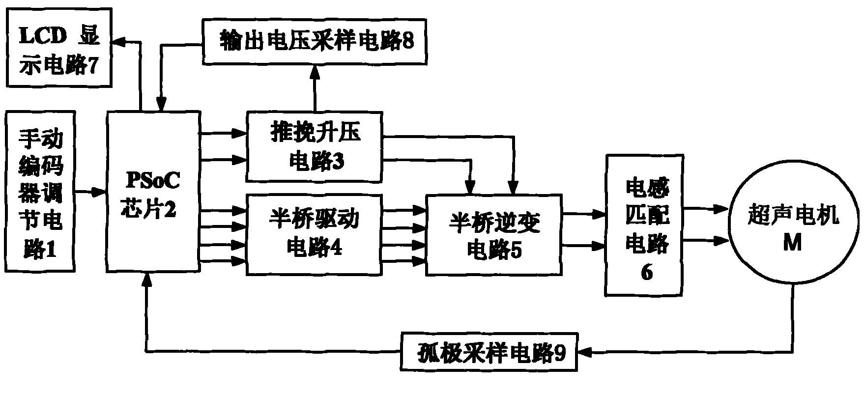
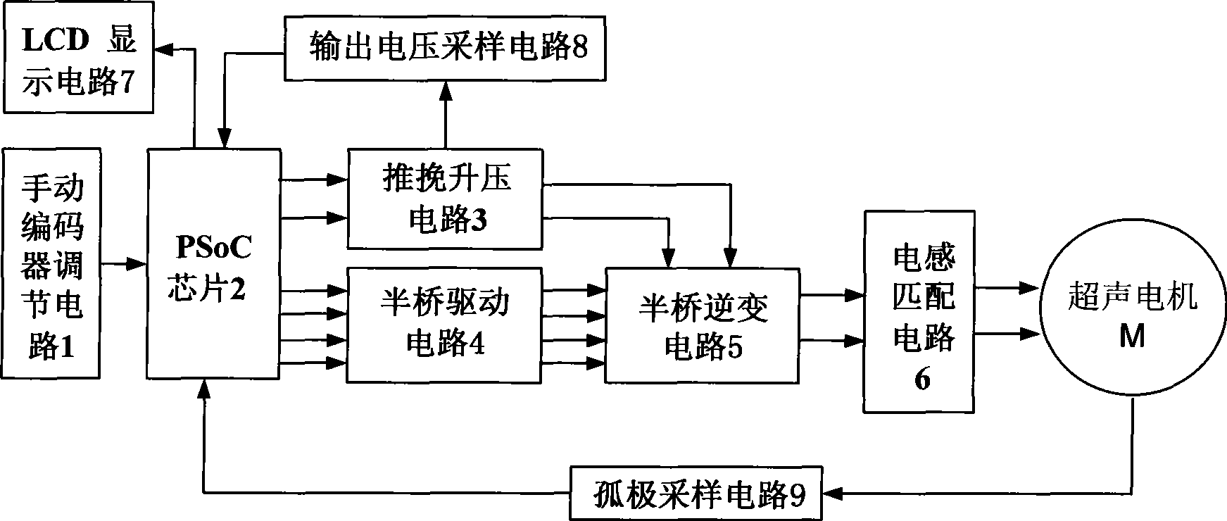
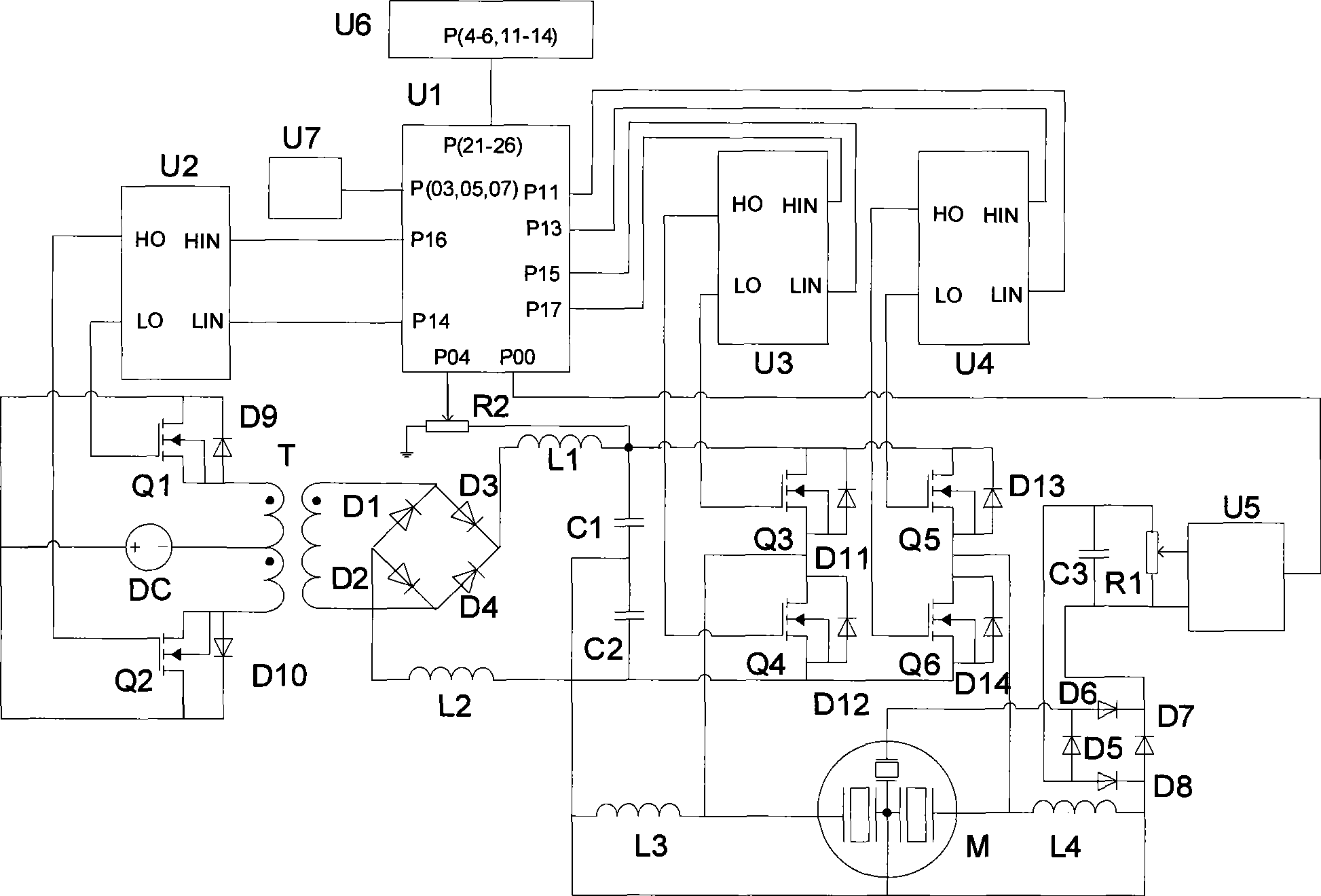
[0018] As shown in Figure 1, an ultrasonic motor drive controller based on an embedded system-level chip includes a manual encoder adjustment circuit 1, a PSoC chip 2, an inductance matching circuit 6, and an LCD display circuit 7, wherein the manual encoder adjustment circuit 1 The output terminal is connected to the input terminal of the PSoC chip 2, the output terminal of the PSoC chip 2 is connected to the input terminal of the LCD display circuit 7, and the output terminal of the inductance matching circuit 6 is connected to the ultrasonic motor M, which is characterized in that it also includes a push-pull boost circuit 3, a half Bridge drive circuit 4, half bridge inverter circuit 5, output voltage sampling circuit 8, isolated pole voltage sampling circuit 9, wherein the input end of push-pull boost circuit 3 and the input end of half bridge drive circuit 4 are respectively connected to PSoC chip 2 The output terminal, the output terminal of the push-pull boost circuit 3...


PUM


Abstract

The invention relates to an ultrasonic motor drive controller based on an embedded type system level chip, which belongs to the ultrasonic motor drive controller and comprises a manual coder regulating circuit, a PSoC, a push-pull boosted circuit, a half-bridge drive circuit, a half-bridge inverter circuit, an inductive matching circuit, an LCD display circuit, an output voltage sample circuit and a single-electrode voltage sample circuit, wherein, the output terminals of the manual coder regulating circuit, the single-electrode voltage sample circuit and the output voltage sample circuit areconnected with the input terminal of the PSoC; the output terminal of the PSoC is connected with the input terminals of the LCD display circuit, the push-pull boosted circuit and the half-bridge drive circuit; the input terminal of the output voltage sample circuit is connected with the output terminal of the push-pull boosted circuit; the output terminals of the push-pull boosted circuit and thehalf-bridge drive circuit are connected with the input terminal of the half-bridge inverter circuit, the output terminal of which is connected with an ultrasonic motor. The input terminal of the single-electrode voltage sample circuit is connected with a single-electrode area of the ultrasonic motor. The ultrasonic motor drive controller can realize the independent regulation of frequency, phase separation and voltage.

Description

technical field [0001] The invention relates to an ultrasonic motor drive controller, in particular to an ultrasonic motor drive controller based on an embedded system level chip. Background technique [0002] Ultrasonic Motor (USM) is a new type of motor made of functional materials. It uses the inverse piezoelectric effect of piezoelectric ceramics and ultrasonic vibration to amplify the microscopic deformation of elastic materials (piezoelectric ceramics, PZT) through resonance and Frictional coupling translates into macroscopic motion of the rotor or slider. Due to its unique operating mechanism, USM has advantages that traditional electromagnetic motors do not have: simple and compact structure, low speed and high torque, no need for deceleration mechanism, flexible and diverse forms, etc. Nanotechnology, military industry, robotics, biology, medical machinery, aerospace, office automation and other fields have shown great application potential and advantages. [0003...

Claims


Application Information

Patent Timeline
Patent Type & Authority Patents(China)
IPC IPC(8): H02N2/00
Inventor 李华峰赵淳生王红占
Owner JIANGSU FENGKE ULTRASONIC MOTORS TECH
Learn More