
Integrated wiring for composite structures

a composite structure and integrated wiring technology, applied in the field of aircraft composite structures, can solve the problems of difficult inspection of the wiring system and structural strength analysis of the composite structure, and achieve the effects of saving weight and cost, further weight savings, and saving weight and cos

Active Publication Date: 2008-08-19
THE BOEING CO
View PDF19 Cites 26 Cited by
  • Summary
  • Abstract
  • Description
  • Claims
  • Application Information

AI Technical Summary

Benefits of technology

The present invention provides a wire that can be integrated with a composite structure material, such as used in airplanes, to save weight and cost. The wire has a conductive core surrounded by an isolation layer made of braided fibers that have similar properties to the composite structure material. This integration eliminates the need for separate wiring support features, such as clips and brackets, which can add further weight to the structure. The technical effect of the invention is to provide a lightweight and cost-effective solution for wiring integration in composite structures.

Problems solved by technology

Currently, wiring systems are generally not “buried” within composite structures, as this could possibly lead to difficulties analyzing structural strength of the composite structure and inspection of the wiring systems.

Method used


Image

  • Integrated wiring for composite structures
  • Integrated wiring for composite structures
  • Integrated wiring for composite structures

Examples


Embodiment Construction

[0023]The present invention is illustrated with respect to a wire 10 for integrating with a composite structure material, particularly suited to the aerospace field. The present invention is, however, applicable to various other uses that may require wiring systems, as will be understood by one skilled in the art. In each of the following figures, the same reference numerals are used to refer to the same components.

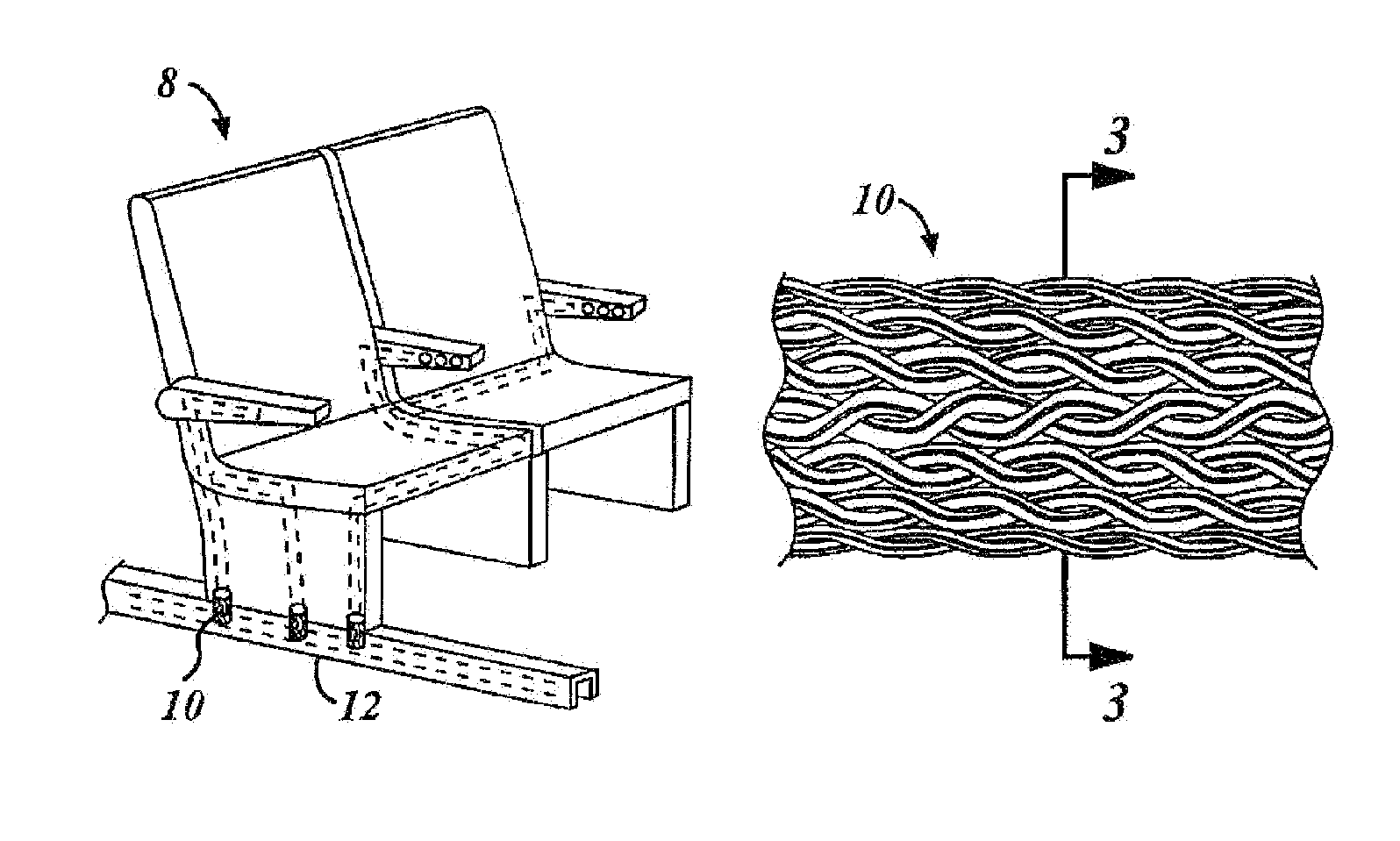
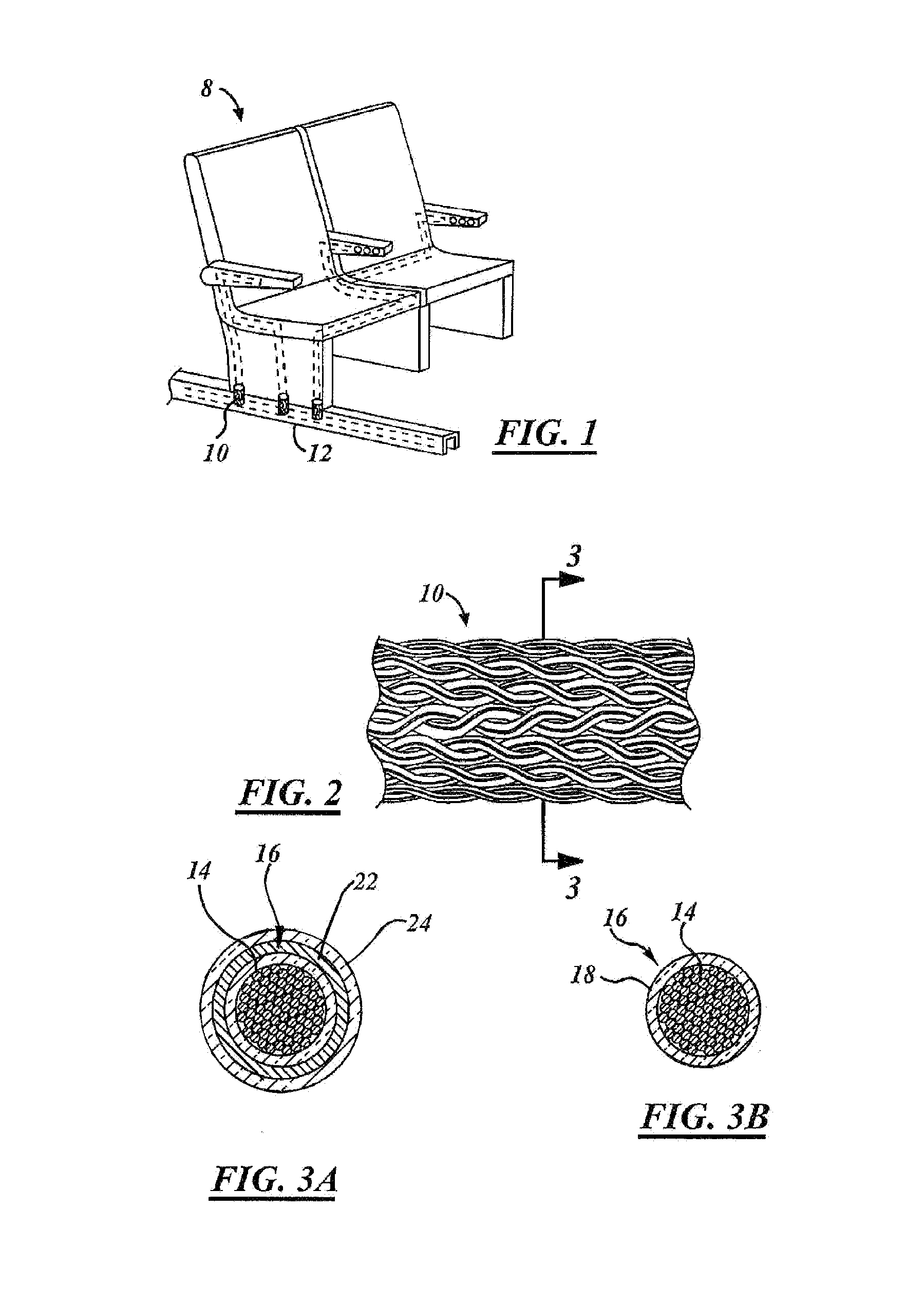
[0024]FIG. 1 illustrates an airplane system 8 including a wire 10 integrated with a composite structure airplane floor panel and seat track 12 (composite structure material). The wire 10 includes fiber-braiding technology of conductive fibers or filaments and electrically insulative fibers, such as glass, for creating a controlled conductive path on the composite structure material.

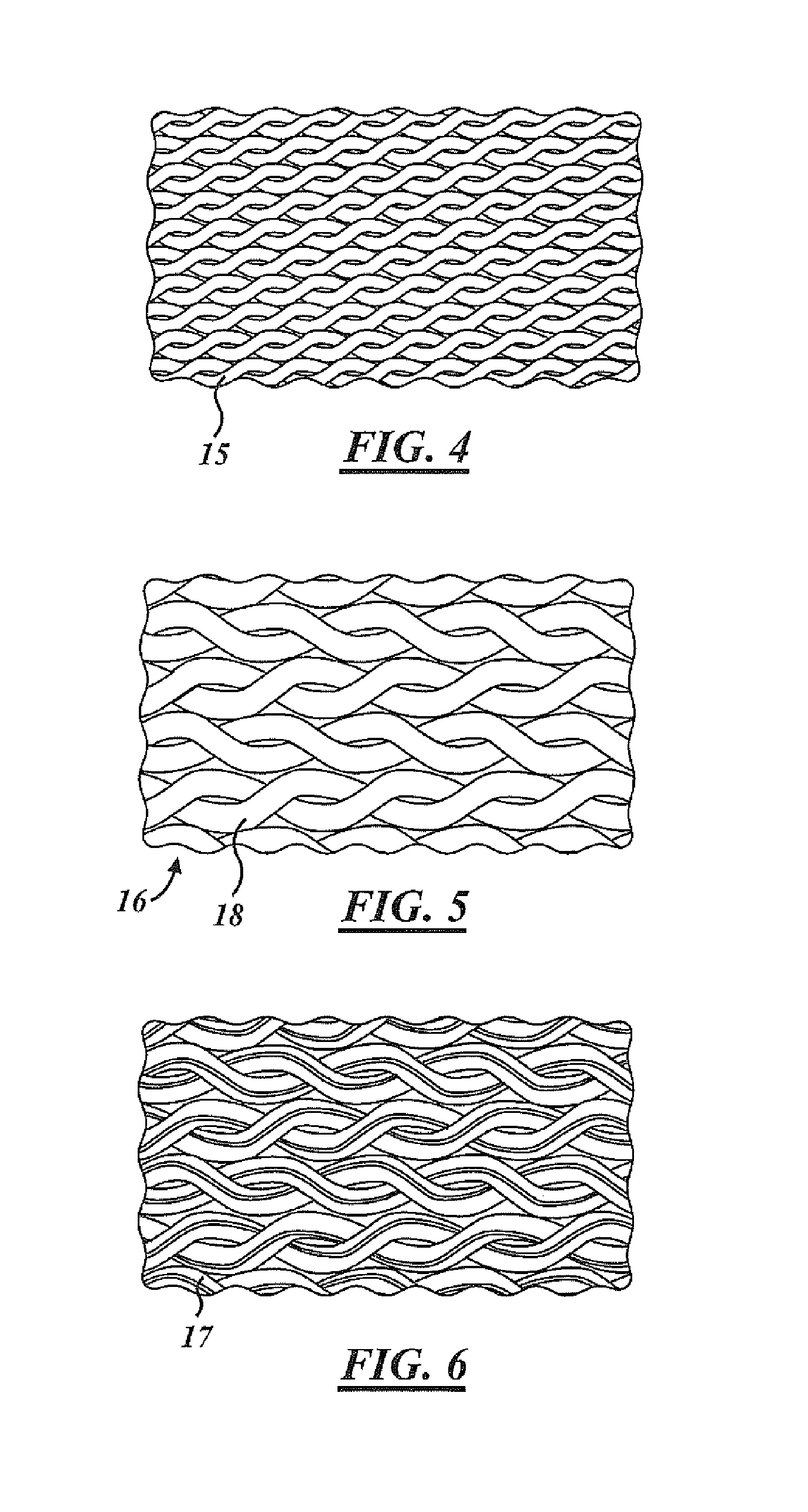
[0025]Referring to FIGS. 2, 3A, and 3B, the wire 10 is illustrated in accordance with further embodiments of the present invention. The wire 10 is impregnated with a resin or an adhesive, howev...


PUM

PropertyMeasurementUnit
conductiveaaaaaaaaaa
non-conductiveaaaaaaaaaa
material propertiesaaaaaaaaaa

Abstract

A wire for integration with an airplane composite structure material includes a conductive core surrounded by an isolation layer for substantially isolating the conductive core from the composite structure material. The isolation layer includes braided fibers, and the braided fibers include a material having at least substantially similar properties as the composite structure material.

Description

TECHNICAL FIELD[0001]The present invention relates generally to an aircraft composite structure and more particularly to wiring integratable with an aircraft composite structure.BACKGROUND OF THE INVENTION[0002]Composite structures include a complex material, such as graphite, in which two or more distinct, structurally complementary substances combine to produce structural or functional properties not present in any individual component. In other words, composite structures have increased strength over the individual components thereof. Generally, the component parts include a composite structure having a core material, a reinforcing material, and a resin binder. Each of these substances alone provides limited strength, but combined properly they become a strong composite structure.[0003]In aircraft construction, composite structures often include various fiber forms and resin combinations in which the fiber form is embedded in the resin while still retaining its identity. Advanced...

Claims


Application Information

Patent Timeline
Patent Type & Authority Patents(United States)
IPC IPC(8): H01B7/00
CPCH01B7/0266H01B7/0861
Inventor GRIESS, KENNETH H.
Owner THE BOEING CO
Learn More