
Arrangement for characterizing and reducing multi-path interference (MPI) and/or optical return loss (ORL) in optical transmission links having multiple discrete reflection sources

a multi-path interference and optical return technology, applied in transmission monitoring/testing/fault-measurement systems, transmission monitoring, electrical devices, etc., can solve the problems of reducing the performance of optical communication systems, affecting the operation of the transmission system, and potentially extremely complex constructive and destructive interference, etc., to achieve the effect of facilitating field simulations

Active Publication Date: 2008-08-19
AT&T INTPROP II L P
View PDF9 Cites 20 Cited by
  • Summary
  • Abstract
  • Description
  • Claims
  • Application Information

AI Technical Summary

Problems solved by technology

Reflections from these discrete reflection sources may degrade the performance of an optical communication system considerably through multi-path interference (MPI).
MPI's effects include constructive and destructive interference that potentially are extremely complex.
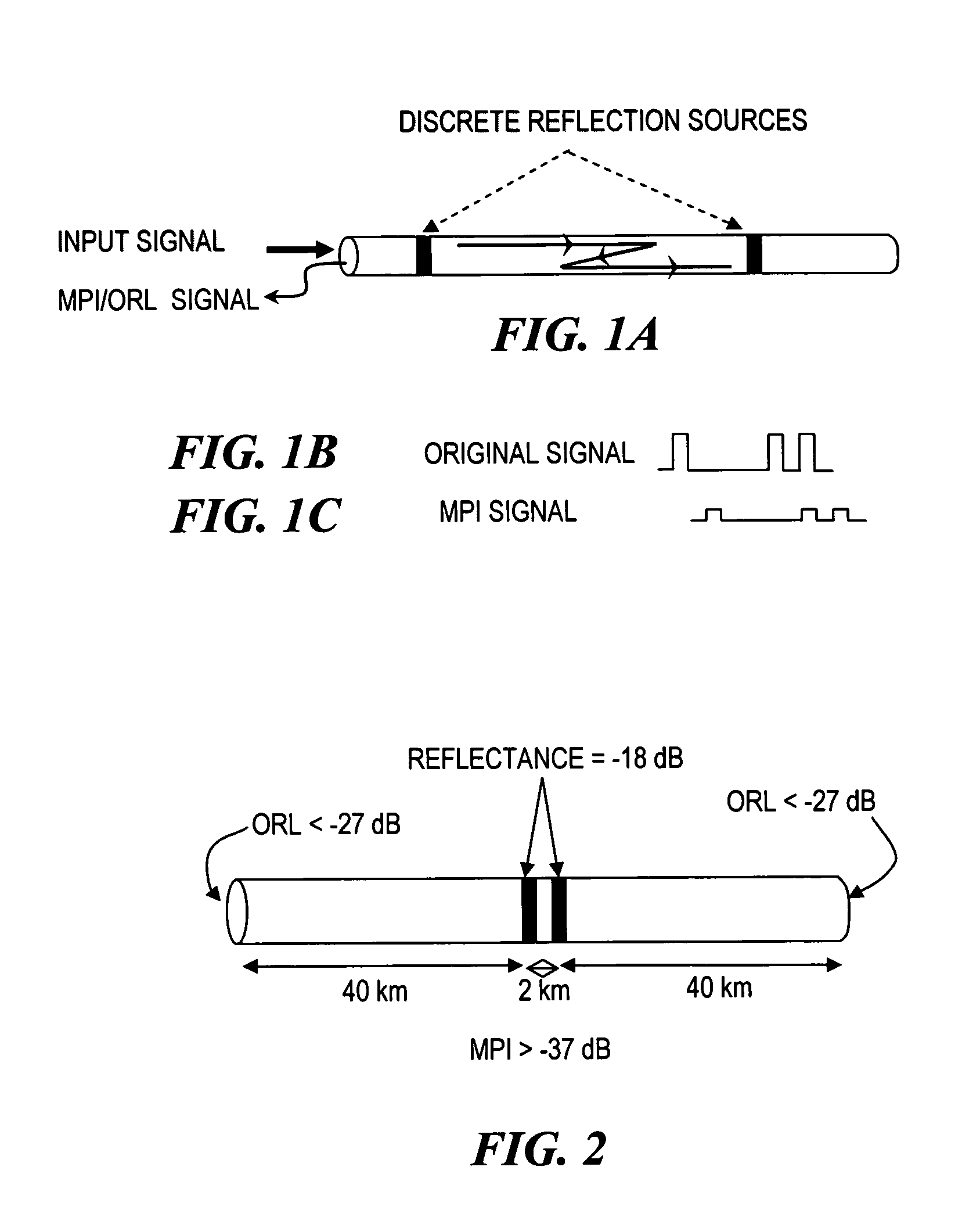
Because the MPI signal co-propagates with the original signal (see FIGS. 1B, 1C) and may also have the same spectral structure as the original signal, direct measurement of MPI in the field is much more difficult than measurement of ORL.
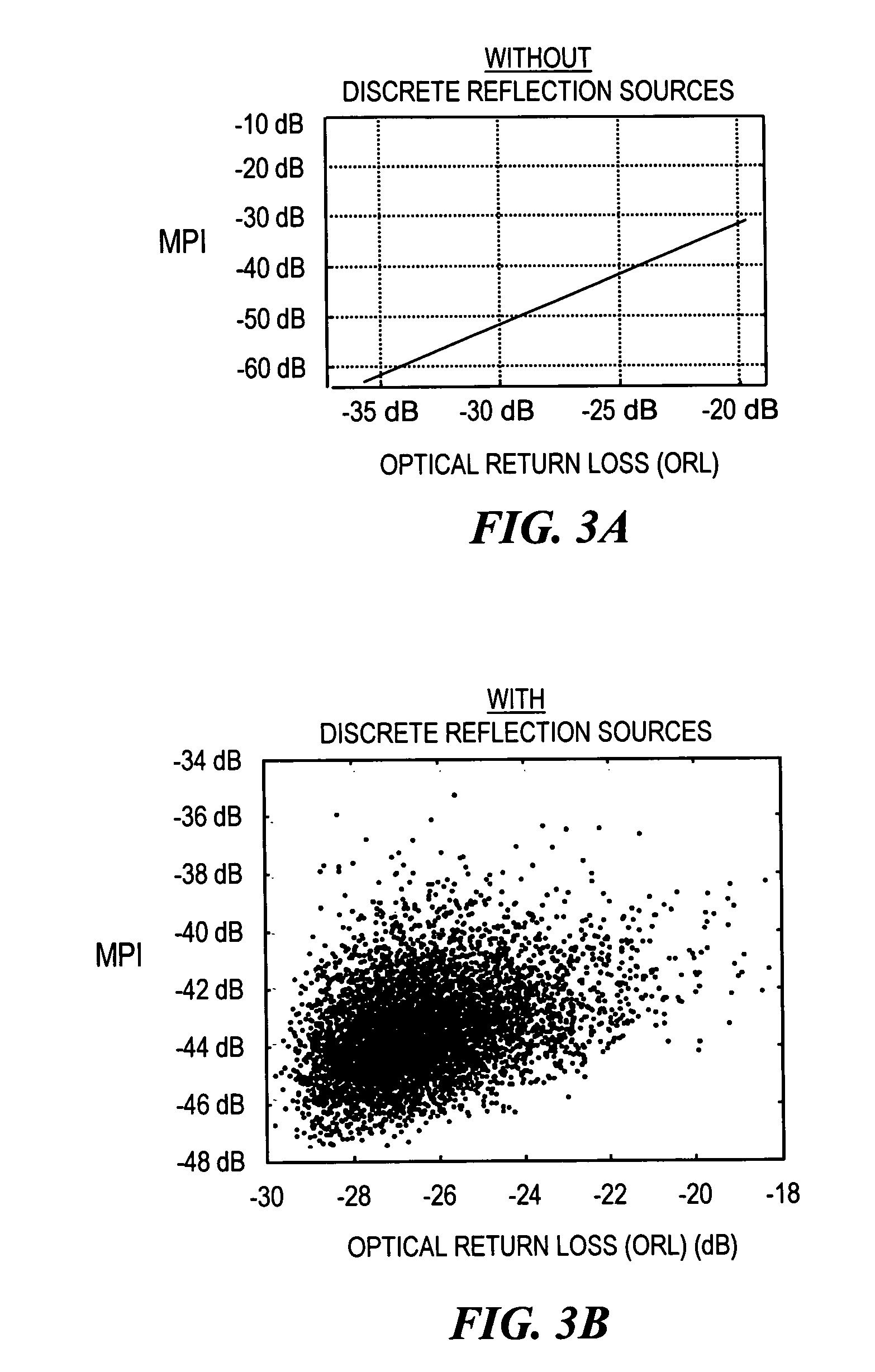
However, recent investigations have revealed that even if the ORL is smaller than −27 dB, MPI can be severe if there are strong discrete reflections in the optical transmission link.
Thus, even for purely EDFA-amplified systems, the level of MPI can be excessive even when ORL is within acceptable limits.
Clearly, this traditional approach is very time consuming and expensive.
Neither the electrical method nor the optical method deal with the problem of turning a fiber link with unacceptably high MPI into a link with acceptable level of MPI, especially doing so at minimal cost.
However, especially in long haul fibers, reducing MPI is not as effective as altogether removing the sources of the MPI in the first place.
Unfortunately, the foregoing approaches do not effectively solve the problem of analyzing a given transmission system to facilitate reduction of MPI to below a given threshold, especially at minimal cost.

Method used


Image

  • Arrangement for characterizing and reducing multi-path interference (MPI) and/or optical return loss (ORL) in optical transmission links having multiple discrete reflection sources
  • Arrangement for characterizing and reducing multi-path interference (MPI) and/or optical return loss (ORL) in optical transmission links having multiple discrete reflection sources
  • Arrangement for characterizing and reducing multi-path interference (MPI) and/or optical return loss (ORL) in optical transmission links having multiple discrete reflection sources

Examples


Embodiment Construction

[0030]In describing embodiments illustrated in the drawings, specific terminology is employed for the sake of clarity. However, the invention is not intended to be limited to the specific terminology so selected, and it is to be understood that each specific element includes all technical equivalents that operate in a similar manner to accomplish a similar purpose. Various terms that are used in this specification are to be given their broadest reasonable interpretation when used to interpret the claims.

[0031]Moreover, features and procedures whose implementations are well known to those skilled in the art are omitted for brevity. For example, the selection, construction and / or use of elements employed in optical communications (such as repeaters, couplers, switches, wavelength blocking elements, terminals, and the like) are readily accomplished by those skilled in the art, and thus their details may be omitted. Also, common network communications techniques and network management t...


PUM


Abstract

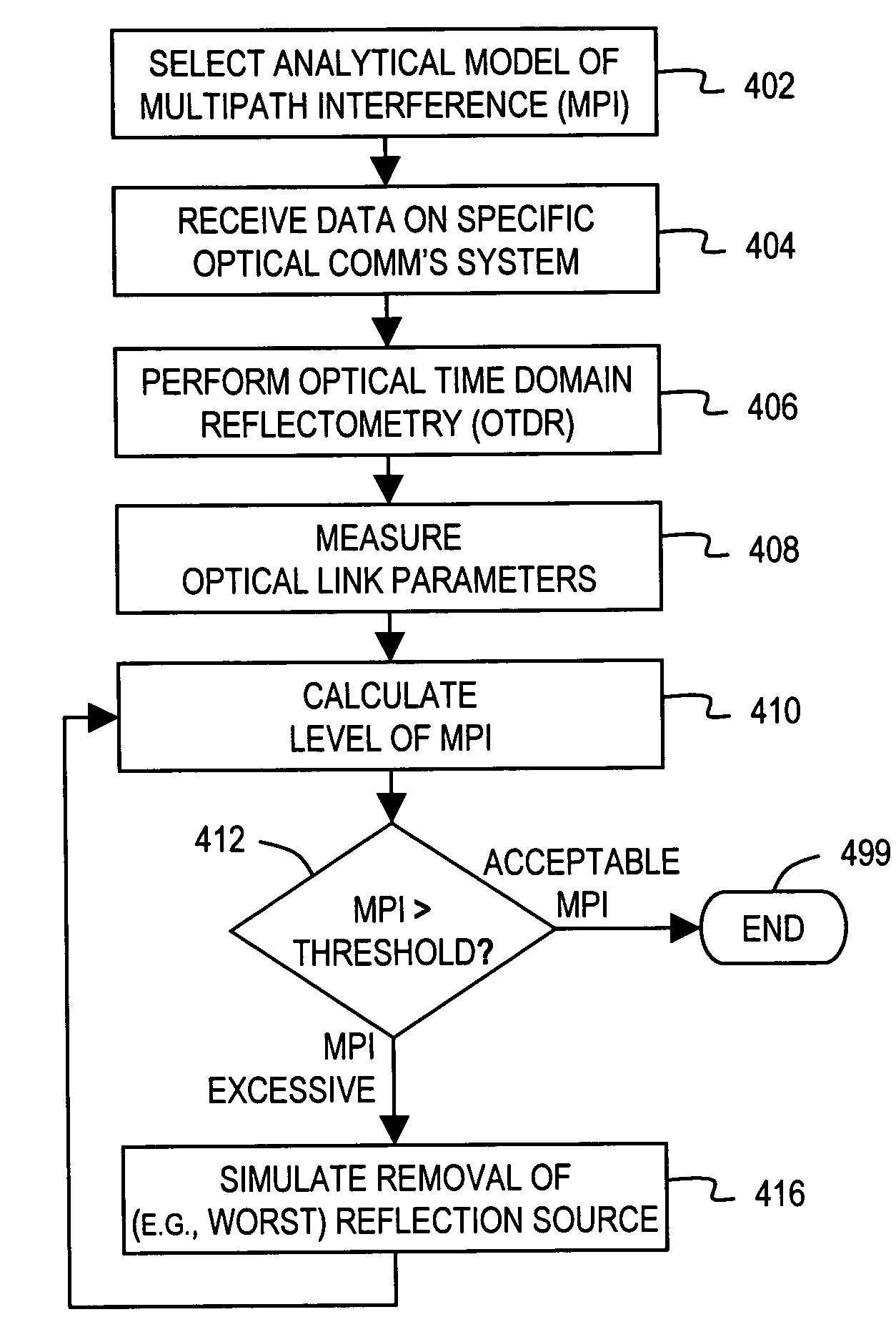
In an optical transmission link having discrete optical reflection sources that cause multi path interference (MPI) and optical return loss (ORL), a method determines how to reduce to beneath a predetermined threshold, a predetermined phenomenon (MPI or ORL or a composite of the two). The method involves (408 / 428 / 458) measuring link parameters of the optical transmission link using an optical reflectometry technique, (410 / 430 / 460) calculating a level of the predetermined phenomenon based on the link parameters, and (416 / 436 / 466) simulating replacement of a number of the reflection sources until the calculated level of the predetermined phenomenon is reduced to less than the predetermined threshold. The method may be performed within a portable optical reflectometry device to facilitate field simulations.

Description

BACKGROUND OF THE INVENTION[0001]1. Field of the Invention[0002]The invention relates to arrangements for characterizing and reducing multi-path interference (MPI) and / or optical return loss (ORL). More specifically, the invention relates to arrangements, especially portable arrangements, for characterizing and reducing MPI and / or ORL in optical transmission links having a single or multiple discrete reflection sources.[0003]2. Related Art[0004]In many optical fiber transmission links, not only is there continuous reflection from the fiber itself, but there are also reflections from discrete reflection sources (see FIG. 1A) such as connectors, mechanical splices or “bad” (reflective) fusion splices. See L. A. Reith, “Issue relating to the performance of optical connectors and splices,”Proc. SPIE, Vol. 1972, pp. 294-305, 1996. Reflections from these discrete reflection sources may degrade the performance of an optical communication system considerably through multi-path interference ...

Claims


Application Information

Patent Timeline
Patent Type & Authority Patents(United States)
IPC IPC(8): H04B10/08
CPCH04B10/071
Inventor BIRK, MARTINZHOU, XIANG
Owner AT&T INTPROP II L P
Learn More