Grill pan

a technology for grilling pans and frying pans, which is applied to frying pans, roasters/grills, kitchen equipment, etc., can solve the problems of preventing food from burning, restricting limiting the cooking range of open flames, so as to enhance the flavor of the foodstuffs cooked ther

Active Publication Date: 2008-08-26
MEYER INTPROP
View PDF17 Cites 49 Cited by
  • Summary
  • Abstract
  • Description
  • Claims
  • Application Information

AI Technical Summary

Benefits of technology

[0010]In the present invention, the first object is achieved by providing a grilling pan having intervening sequences of elevating ribs that are tilted slightly such that an intervening channel drains toward a large fat or grease collecting channel at the edge of the pan. At least some of the ribs have holes or slits formed in them to provide direct or radiant cooking from the flame or other heating source below the grilling pan. By disposing the slits or holes on ribs that are slightly below adjacent ribs that are solid, most of the fat is drained away, while a minor portion escapes through the slits and enhances the flavor of the foodstuffs cooked thereon.

Problems solved by technology

Open flame cooking is generally limited to outdoor cooking, as special venting is needed to exhaust the smoke and flames produced by burning fat.
However, certain foods are particularly difficult to cook over an open flame.
However, such grill pans do not prevent the burning of foods if the cook is not alert and ready to move the pan as dripping grease cause large flares.
Alternatively, when such pans utilize a flat surface, to facilitate the removal and turning of delicate food with a spatula, the holes are readily clogged by the food, and hence the food is more likely to be at least partially braised in liquid rather than seared.
However, such grill pans do not achieve the flavor of open flame cooked foods, even when used under an oven broiler, as some burning and sizzling of the fat in an open flame flavors the meat.
However, in either case a considerable quantity of fat is liable to drip out through the slots, if they are oriented to allow direct expose to the flame.

Method used


Image

  • Grill pan
  • Grill pan
  • Grill pan

Examples


Embodiment Construction

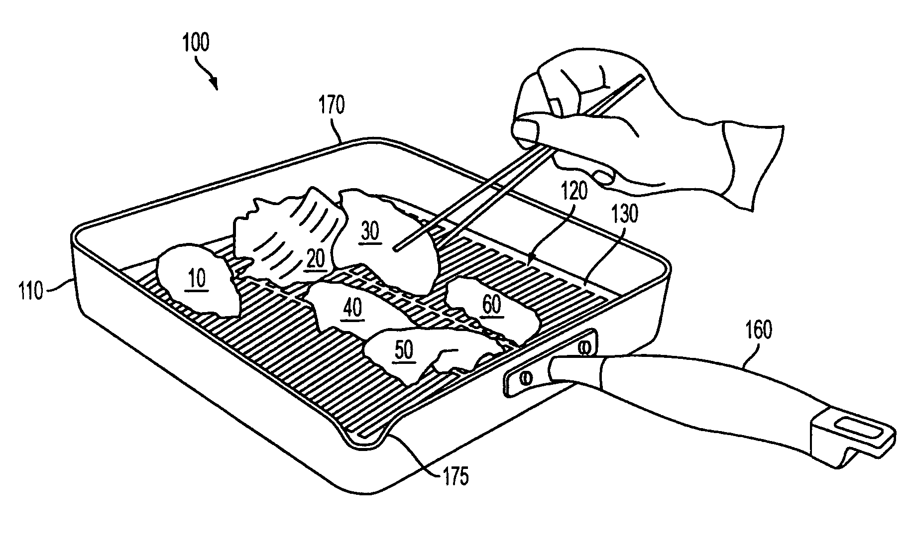
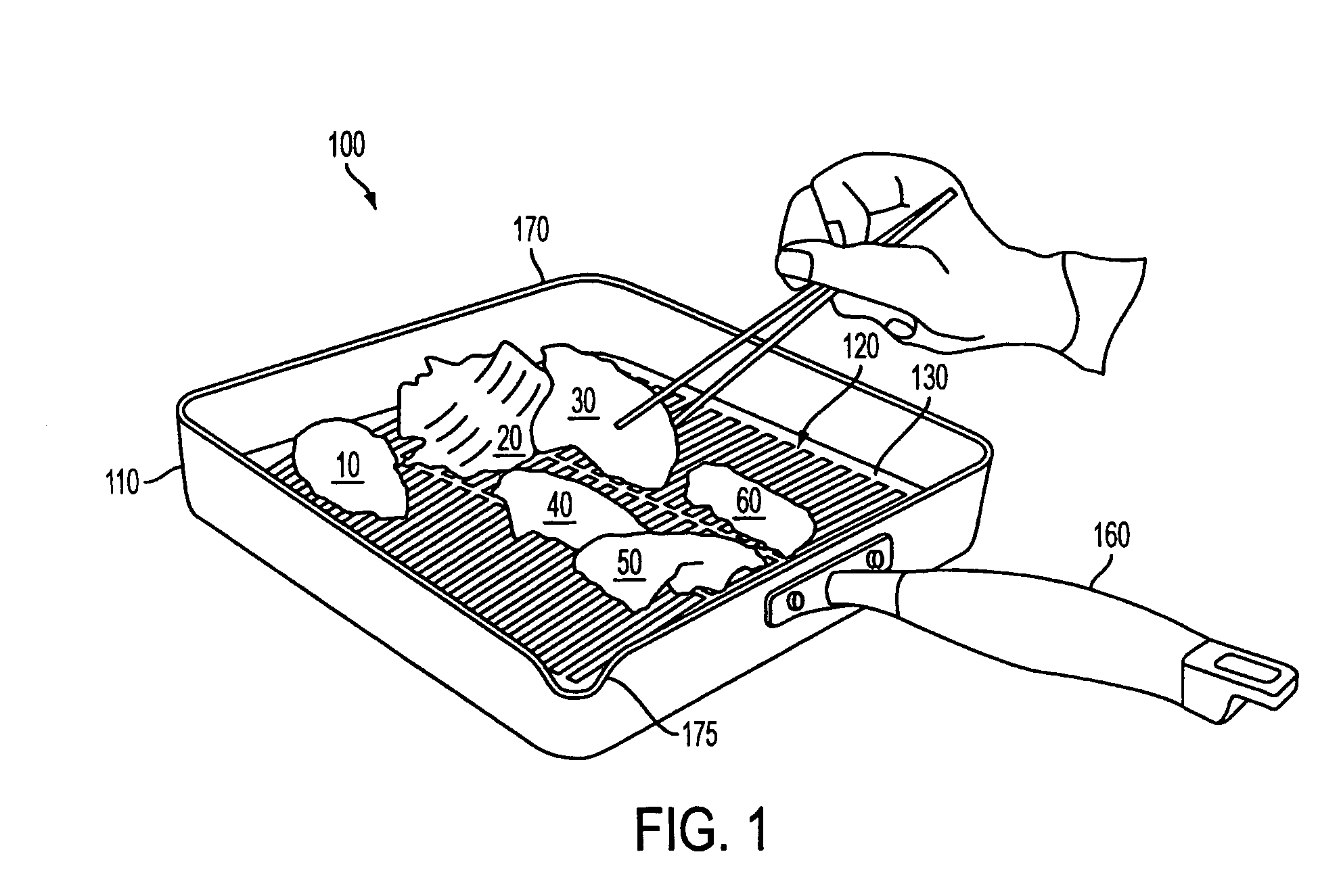
[0024]In accordance with the present invention, FIG. 1 is a perspective view showing a first embodiment of a grilling pan in use while the chef is preparing a variety of foodstuffs. The foodstuffs 10, 20, 30, 40, 50 and 60 are disposed on the supporting grill section 120 of grill pan 100. An attached and integral fat or grease-collecting channel 130 surrounds grill section 120. Substantially vertical walls 110 that form the perimeter of the grill pan in turn surround channel 130. The grill pan is readily moved about via handle 160, which in turn is attached to vertical wall 110. The grill section 120 includes a series of support ribs that slope downward from an apex or ridge in the top of grill section 120. The ribs are oriented parallel to the slope formed in grill surface 120 such that the intervening regions between the ribs form a series of parallel channels for draining liquids into the surrounding collecting channel 130. Grill pan 100 also includes a pouring spout 175 formed i...


PUM


Abstract

A grill surface or pan provide for the removal of fats and oils by supporting the foodstuffs on ribs that slope downward such that the intervening regions form channels for transporting fluids to the edge of the pan, and away from the cooking food stuffs. The draining channels are interrupted by intervening ribs of a lower height than the first set of foodstuff supporting ribs. The intervening ribs have a series of slits or holes formed in there apex to enable the direct cooking of the foodstuff by radiant heat from a flame or heating source disposed underneath the grill surface. The grill surface may be combined in a pan that provides a peripheral fluid collecting channels at the termination or junction of the draining channels disposed between the sets of rib food supporting and slotted or perforated ribs.

Description

CROSS REFERENCE TO RELATED APPLICATIONS[0001]This application claims priority from U.S. Provisional Patent Application Ser. No. 60 / 554,734, filed Mar. 19, 2004, the disclosure of which is incorporated herein by reference in its entirety.BACKGROUND OF INVENTION[0002]The present invention relates to improved surfaces and pans for grilling foods.[0003]Prior methods of grilling foods involve either pacing food on a wire mesh over an open flame, or a cooking at high temperatures in enclosed pan, the pan having a series of ribs for searing the food in contact therewith, emulating in part the action of the wire mesh in open flame cooking. In the former case fat and liquid is removed from the foods by dripping through the mesh into the flame. In the latter case of pan grilling, the ribs or pan surface is situated to drain the fat away from the food being cooked, lest it reach the level of the supporting ribs and simmer rather than sear the food surface.[0004]Open flame cooking is generally ...

Claims


Application Information

Patent Timeline
Patent Type & Authority Patents(United States)
IPC IPC(8): A47J37/00A47J37/06A47J37/10
CPCA47J37/108A47J37/067A47J37/10
Inventor CHENG, STANLEY KIN SUI
Owner MEYER INTPROP
Why Eureka
Try Eureka