
Piston for internal combustion engine, compressor or the like

a technology for internal combustion engines and compressors, applied in the direction of trunk pistons, combustion engines, plungers, etc., can solve the problems of insufficient reduction of column friction loss increased load and stress, and relatively low heat removal effect, etc., to achieve tremendous reduction of friction coefficient between piston skirts and cylinder walls, save fuel, and protect the environment

Inactive Publication Date: 2008-08-26
CHEN MARINA LING +1
View PDF9 Cites 10 Cited by
  • Summary
  • Abstract
  • Description
  • Claims
  • Application Information

AI Technical Summary

Benefits of technology

[0006]An object of the present invention is to provide a piston for internal combustion engine, compressor or the like that substantially reduces the power loss due to friction and heat, improve the output power, and reduce the power consuming, noise and exhaust.
[0007]Another object of the present invention is to constantly supply, collect, and reserve lubricant on the piston skirt, store and distribute sufficient lubricant in the clearance between piston skirt and cylinder wall, in order to reduce the friction. The result is to improve the output power of internal combustion engine, reduce the fuel consuming, noise and exhaust, and finally to achieve fuel saving and environment protection.
[0010](b) reserving lubricant in one or more lubricant reservoirs provided on the outer surface of the piston skirt to maintain lubrication between the piston skirt and cylinder wall so as to reduce a friction between the cylinder and the piston skirt, reduce loss of power due to friction and heat, improve the output power of internal combustion engine, compressor or the like, reduce the fuel consuming, noise and exhaust, and achieve fuel saving and environment protection.
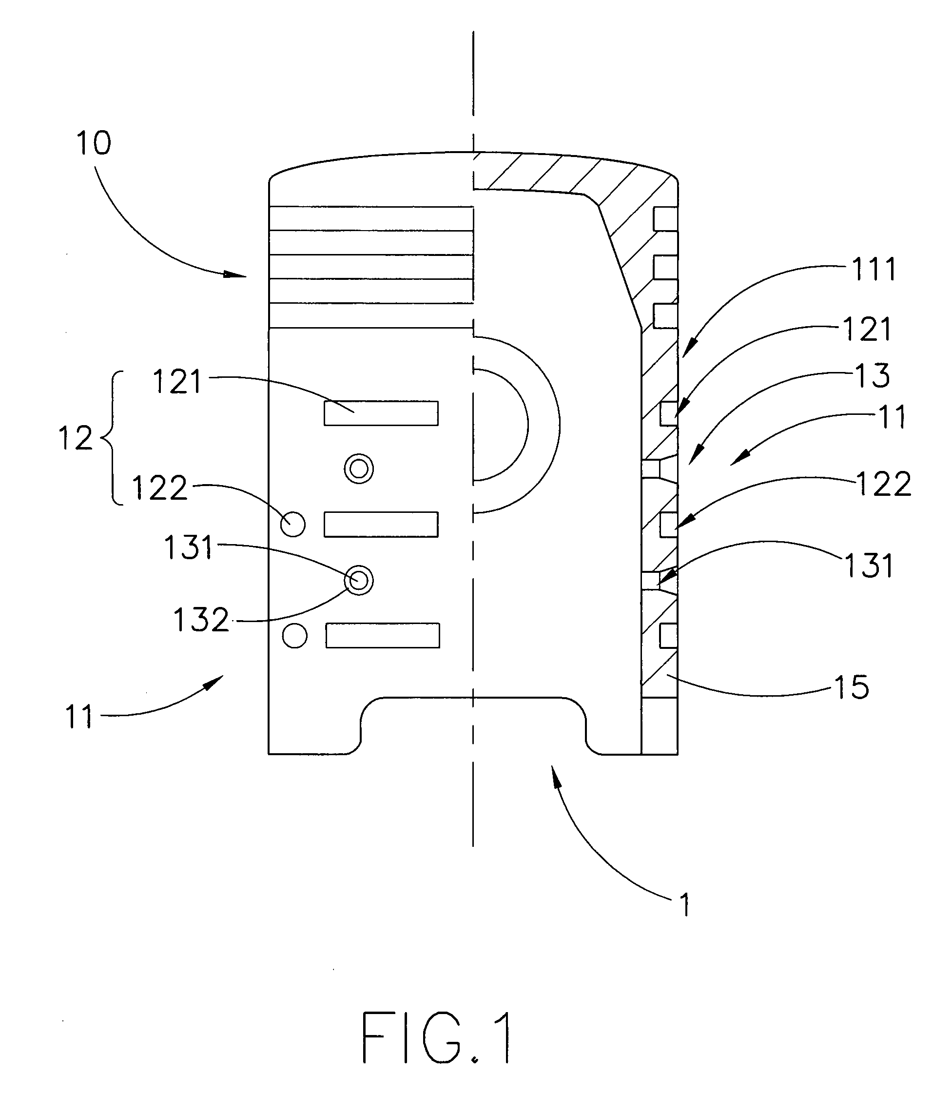
[0013]According to the present invention, when the internal combustion engine or the compressor is idle, the piston in the axial direction has no movement. Due to the film tension of the oil film formed between the outer surface of the piston skirt and the cylinder wall, the piston skirt grooves and piston skirt indentions are filled with contracted lubricant. When the engine starts, due to the lubricant reserved and filled in the space between the piston skirt and the cylinder wall, the direct contact of the piston skirt and the cylinder wall is prevented and thus the coefficient of friction of the piston skirt and the cylinder wall is tremendously reduced, resulting in fuel saving and environment protection.
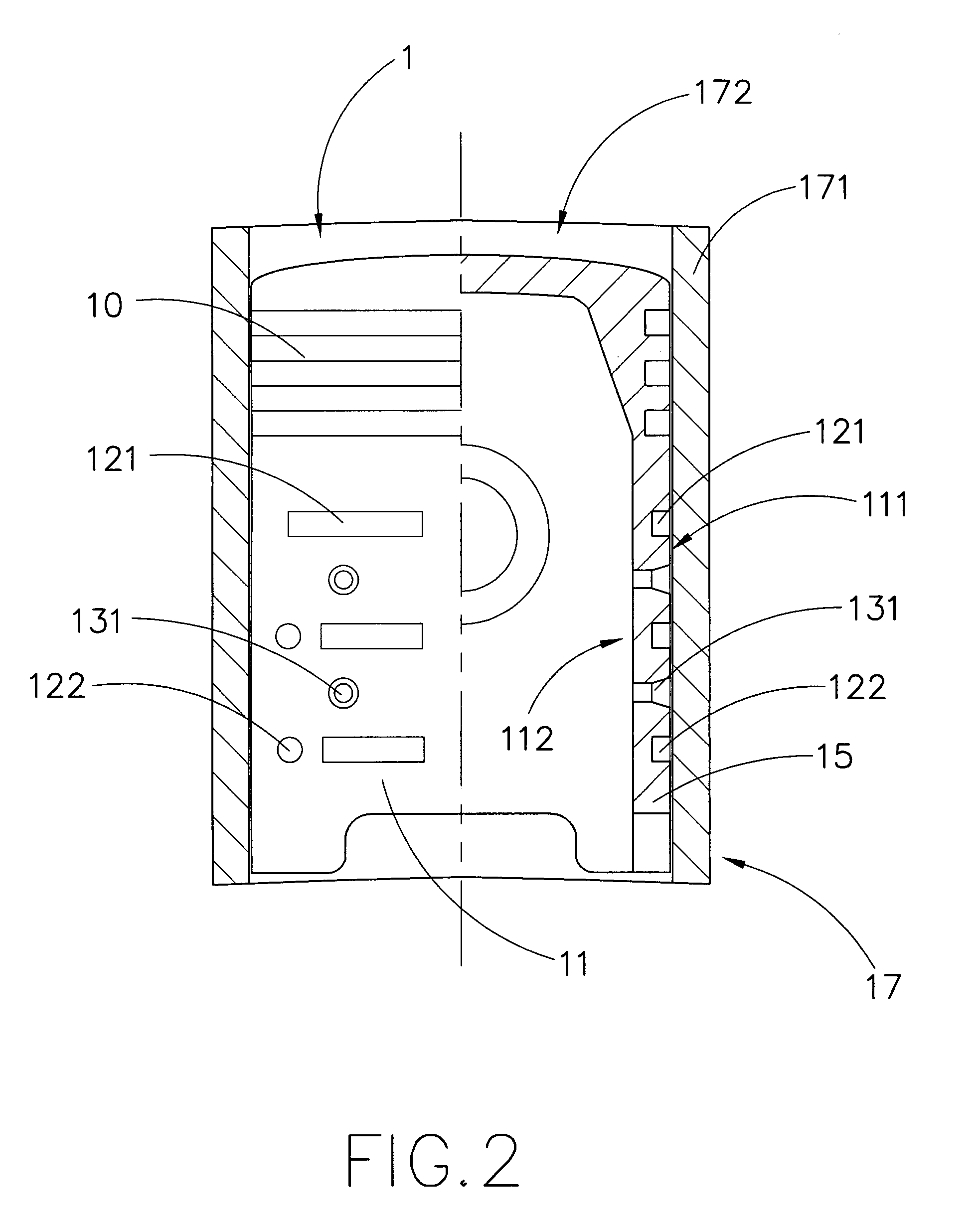
[0014]When the piston of internal combustion engine or compressor is moving along the axial direction at high speed, the piston expands because of heat. The piston and the cylinder wall form a preferred clearance as designed to work in the best condition for lubrication and piston alignment. The lubricant constantly flows to the piston skirt through the through holes and is transferred and reserved in the grooves and indentions on the piston skirt, the reserved lubricant also distributes around the piston skirt, so that the lubricant between piston skirt and cylinder wall can always form a fluidic oil film. This will reduce the power loss due to friction and heat and thus improve the output power of internal combustion engine, compressor or the like, reduce the fuel consuming, noise and exhaust, and achieve fuel saving and environment protection.

Problems solved by technology

Since the piston works under high temperature, high pressure and high speed condition, it is badly heated but its heat removal effect is relatively low due to its inherent structure.
Working under such severe circumstance will cause deformation and more friction, resulting in additional load and stress.
Although piston is always considered to be important during the development of internal combustion engine technique, the column friction loss between piston skirt and cylinder wall can't be sufficiently reduced due to the inherent structure.
If the column area between piston skirt and cylinder wall is too small, it can't align the movement steadily; if the column area between piston skirt and cylinder wall is too big, it will increase friction loss.
Since the space between piston skirt and cylinder wall is very small, the failure of forming a lubricant film during high speed movement is the major reason of deformation and heavy wear.
As a result, the output power of the internal combustion engine is seriously affected.

Method used


Image

  • Piston for internal combustion engine, compressor or the like
  • Piston for internal combustion engine, compressor or the like
  • Piston for internal combustion engine, compressor or the like

Examples


Embodiment Construction

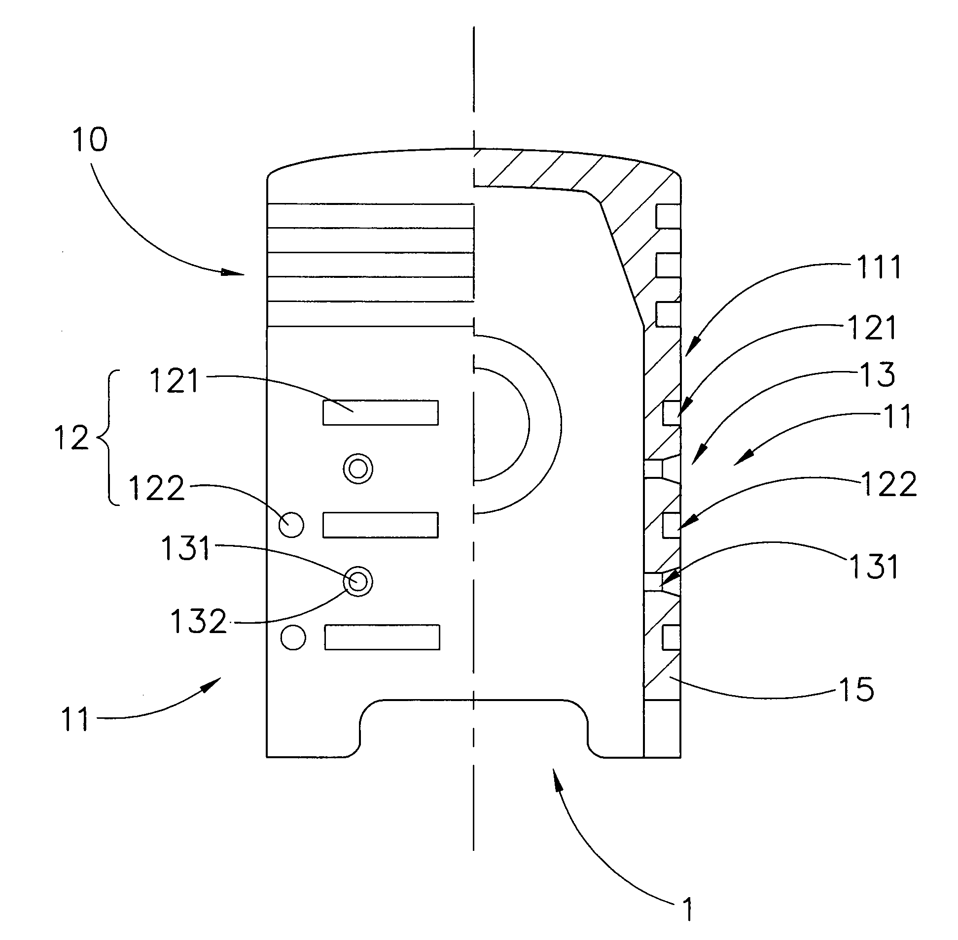
[0021]Referring to FIGS. 1 and 2, a piston 1 for internal combustion engine, compressor or the like according a preferred embodiment of the present invention is illustrated. The piston 1 according to the present invention comprises a piston ring 10 and piston skirt 11 having a piston skirt wall 15. One or more lubricant reservoirs 12 and channels 13 are provided on an outer surface 111 of the piston skirt 11. In one embodiment, the lubricant channels 13 are through holes 131 and the lubricant reservoirs 12 comprise grooves 121 and indentions 122 provided on the piston skirt 11. The piston skirt grooves 121 and indentions 122 are arranged to reverse the lubricant while the through holes 131 supply lubricant.

[0022]It is preferable that the elongated grooves 121 are arranged to be extended radially and intervally around the piston skirt 11 and the circular indentions 122 are arranged to be positioned between two opposing ends of the two grooves 121. The through holes 131 are provided a...


PUM


Abstract

A piston for internal combustion engine, compressor or the like, includes a piston ring, a piston skirt having a piston skirt wall. One or more lubricant channels and reservoirs are provided on an outer surface of the piston skirt. Lubricant is conducted to an outer surface of a piston skirt of a piston through the lubricant channels which are communicating an inner surface of the piston skirt with the outer surface thereof. The lubricant is able to be reserved in the lubricant reservoirs provided on the outer surface of the piston skirt to maintain lubrication between the piston skirt and cylinder wall so as to reduce a friction between the cylinder and the piston skirt, reduce loss of power due to friction and heat, improve the output power, reduce the fuel consuming, noise and exhaust, and achieve fuel saving and environment protection.

Description

BACKGROUND OF THE PRESENT INVENTION[0001]1. Field of Invention[0002]This present invention relates to piston structure and more particularly to a piston for internal combustion engine, compressor or the like which is capable of reducing the friction between the piston and the cylinder wall and the method thereof.[0003]2. Description of Related Arts[0004]Piston is the “heart” of an internal combustion engine. It needs to withstand the alternating mechanical and thermal loads. As one of the key components of internal combustion engine it works in the toughest condition. A piston has to keep air pressure and transmit the force to a connecting rod through a pin to rotate a crankshaft. Since the piston works under high temperature, high pressure and high speed condition, it is badly heated but its heat removal effect is relatively low due to its inherent structure. Working under such severe circumstance will cause deformation and more friction, resulting in additional load and stress. It...

Claims


Application Information

Patent Timeline
Patent Type & Authority Patents(United States)
IPC IPC(8): F02F3/00
CPCF16J1/08F16J1/04
Inventor CHEN, MARINA LINGWANG, DEHENG
Owner CHEN MARINA LING
Learn More