

Electrical connector
- Summary
- Abstract
- Description
- Claims
- Application Information
AI Technical Summary
Benefits of technology
Problems solved by technology
Method used
Image

Examples
Embodiment Construction
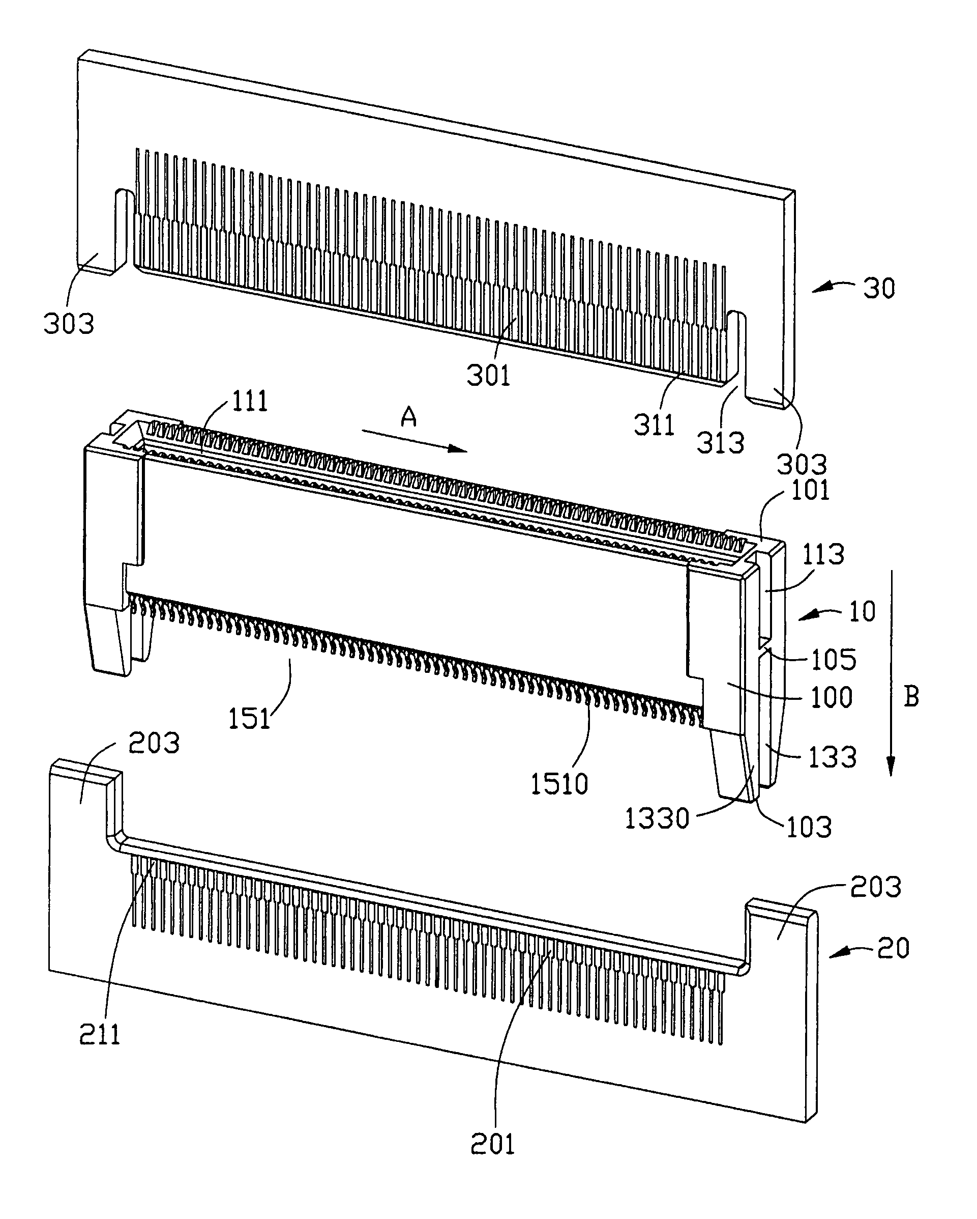
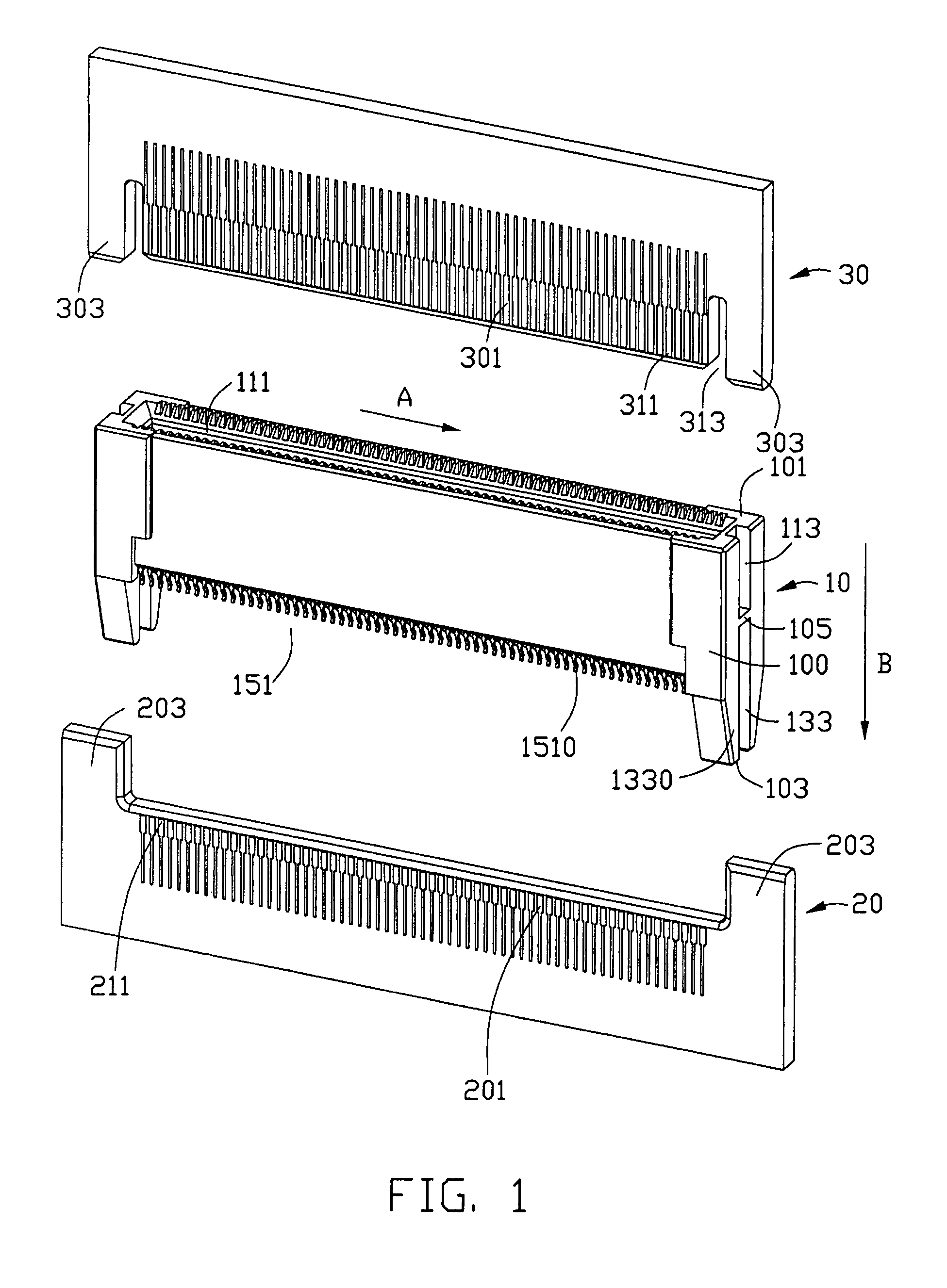
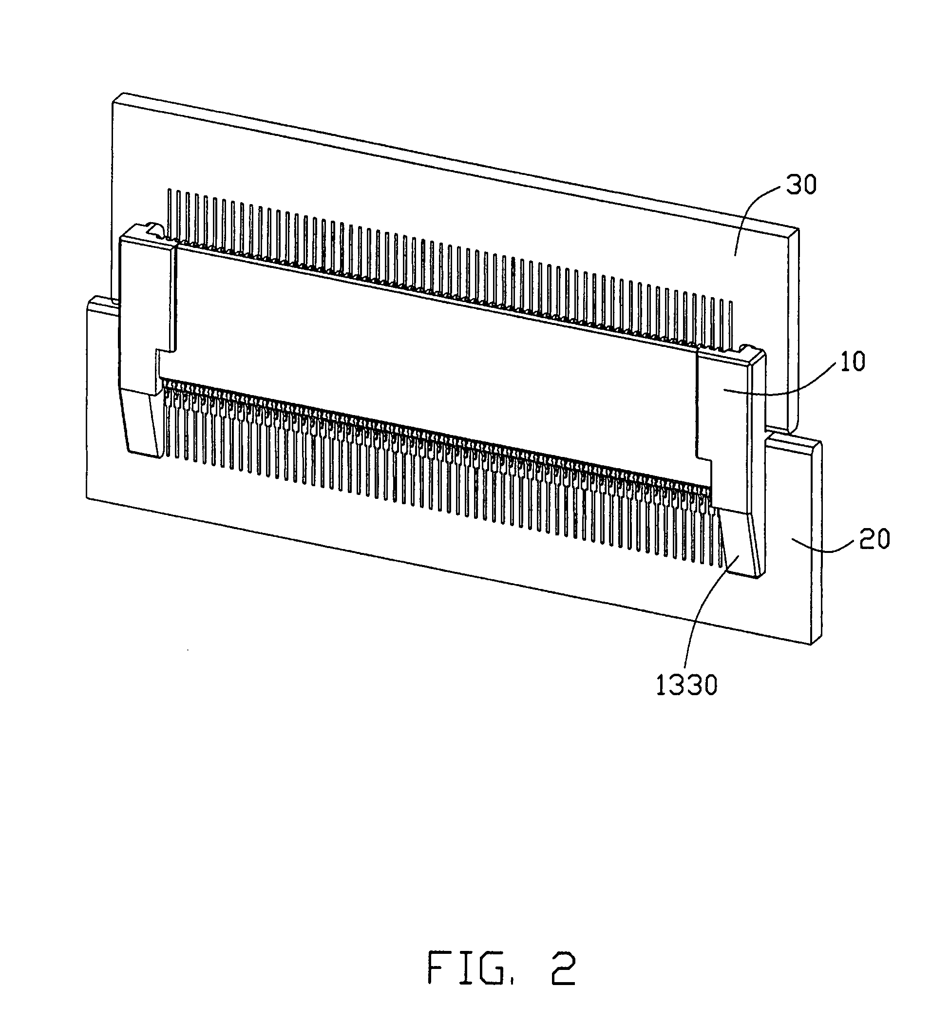
[0016]Referring to FIGS. 1 to 5, an electrical connector 10 for electrically connecting with two circuit boards, generally a parallel arrangement of a mother-card member 20 and a daughter-card member 30, is shown according to a preferred embodiment of the present invention. In this embodiment, the mother-card member 20 defines a mating edge 201 where a plurality of soldering pads 211 is disposed thereon, and two lateral edge portions 203 extending outwardly with a predetermined distance from the mating edge 201 of the mother-card member 20. In other words, the mating edge 201 is recessed with respect to the lateral edge portions 203 of the mother-card member 20. The daughter-card member 30 defines a mating edge 301 where a plurality of soldering pads 311 is disposed thereon, and two lateral edge portions 303 on opposed ends of the mating edge 301 of the daughter-card member 30. The lateral edge portions 303 are laterally spaced from the mating edge 301 by elongated slots 313 defined...
PUM
 Abstract
Description
Claims
Application Information