Gear shift control system of hybrid vehicle

a technology of gear shifting control and hybrid vehicles, applied in the field of gear shifting control system of hybrid vehicles, can solve the problems of increasing the time required for gear shifting and the need for synchronization of rotation for a longer time, and achieve the effect of synchronizing the time for the gear setting and quick gear shifting

Active Publication Date: 2008-08-26
VOLVO LASTVAGNAR AB
View PDF9 Cites 14 Cited by
  • Summary
  • Abstract
  • Description
  • Claims
  • Application Information

AI Technical Summary

Benefits of technology

[0005]It is therefore an object of the present invention to reduce as much synchronization time as possible at the time of gear shifting for performing a quick gear shift.
[0007]Accordingly, when a request of gear shifting occurs, the gear position is set to a neutral position once and then, the rotating electric machine operates in the motor mode or the power generating mode to realize a rotational speed of the input shaft of the transmission corresponding to the requested gear position, so that the rotational speed of the input shaft of the transmission is quickly converged to a region of the synchronizing rotational speed. As a result, at the time of the gear shifting, synchronizing time for the gear setting is reduced, allowing the quick gear shift.

Problems solved by technology

In such a hybrid system, an inertia force caused by the rotating electric machine connected to an input shaft of the transmission is applied at the time of the gear shift of the transmission and therefore, synchronization of rotation needs longer time, thus increasing time required for the gear shift.

Method used


Image

  • Gear shift control system of hybrid vehicle
  • Gear shift control system of hybrid vehicle
  • Gear shift control system of hybrid vehicle

Examples


Embodiment Construction

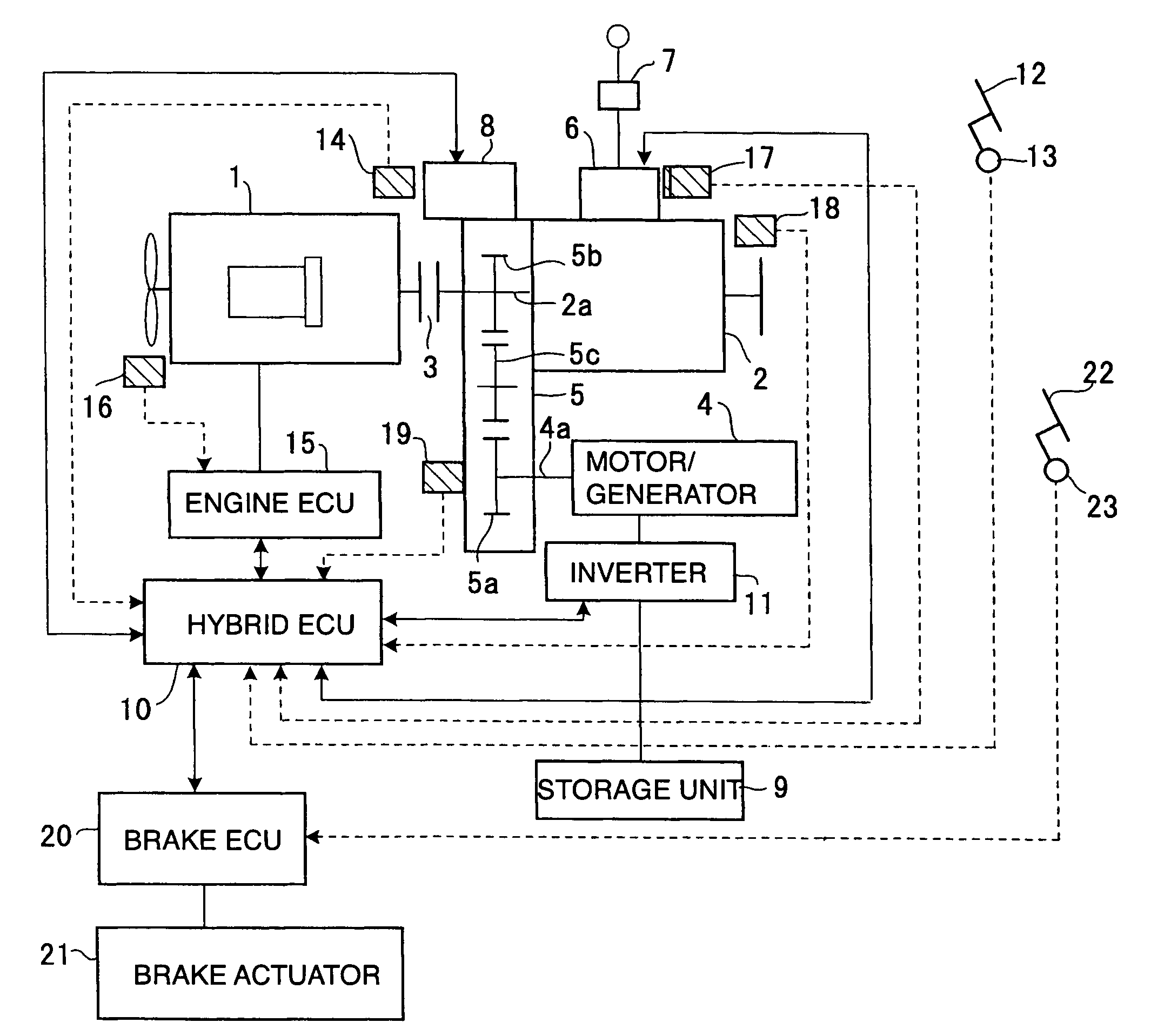
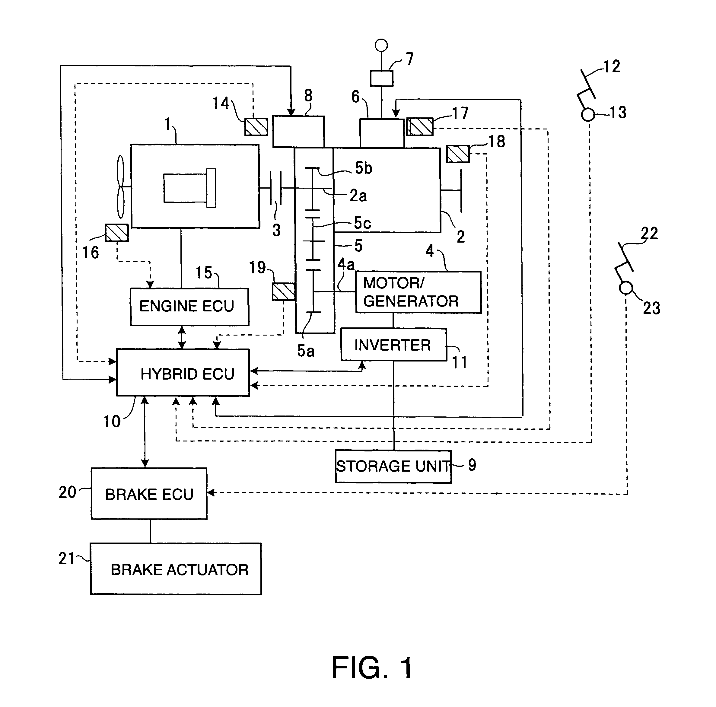
[0012]In FIG. 1, the reference numeral 1 denotes an engine and the reference numeral 2 denotes a gear-type transmission. A friction clutch 3 is interposed between an input shaft of the engine 1 and an input shaft 2a of the transmission 2.

[0013]A diesel engine or an engine using Compressed Natural Gas (CNG) as fuel) may be used as the engine 1. The reference numeral 4 denotes a rotating electric machine (motor / generator), which serves as an electric generator and an electric motor. An input / output shaft 4a of the rotating electric machine 4 is coupled to an input shaft 2a of the transmission 2 via a rotation transmission mechanism 5, a gearbox.

[0014]The transmission 2 is provided with a control unit 6 to control a gear shift thereof. The control unit 6 is connected to a change lever unit 7 and a hybrid electronic control unit 10 (hybrid ECU). When the change lever unit 7 generates a gearshift command, the transmission 2 is controlled according to a signal from the hybrid ECU 10 to es...


PUM


Abstract

In a hybrid-drive electric vehicle, upon request of gear shifting of a transmission (2), a clutch (3) is first disconnected and the transmission (2) is set to a neutral position. The rotating electric generator 4 is then operated in a motor mode or a power generating mode so that a rotational speed of an input shaft of the transmission (2) reaches a region of a synchronizing rotational speed in accordance with a requested gear position. When the rotational speed of the input shaft of the transmission (2) reaches the region of the synchronizing rotational speed, the gear position of the transmission (2) is changed over from the neutral position to the requested gear position. Thus the rotation synchronizing time for the gear shifting in the transmission (2) is reduced, making it possible to perform the gear shifting for a short period of time.

Description

TECHNICAL FIELD[0001]The present invention relates to a vehicle which is provided with a parallel type of hybrid drive system comprising an engine and a rotating electric machine (motor / generator) as power sources of the vehicle and in particular to a gearshift control system of a transmission for the same.BACKGROUND OF THE ART[0002]In order to drive a vehicle, a hybrid drive system provided with an engine and a motor has been proposed by Japanese Patent Laid-Open Publications No. 10-304513 and No. 2001-103603.[0003]In addition, it is known that a clutch is interposed between an engine and a transmission and a rotating electric machine having functions of an electric motor and an electric generator is coupled to an input side of the transmission.[0004]In such a hybrid system, an inertia force caused by the rotating electric machine connected to an input shaft of the transmission is applied at the time of the gear shift of the transmission and therefore, synchronization of rotation n...

Claims


Application Information

Patent Timeline
Patent Type & Authority Patents(United States)
IPC IPC(8): B60W10/08B60K6/48B60K6/547B60L50/16B60W10/02B60W10/10B60W20/00F16H3/12F16H61/04
CPCB60K6/48B60W10/02B60W10/10F16H61/0403B60K6/547Y10T477/6403B60L2240/486B60W20/00B60W2710/1011F16H3/126F16H2061/0422F16H2306/48Y02T10/6221Y10T477/75Y10T477/78Y10T477/6418Y10T477/26Y10T477/743Y10T477/638Y10T477/641Y10T477/6428Y10T477/76B60K6/28B60L2240/421B60W10/08B60W2540/10B60W2540/12B60W2710/081B60L50/40Y02T10/62Y02T10/64Y02T10/70B60W20/30B60W20/40B60W10/06B60K6/365
Inventor NISHINA, MITSUHIROSUZUKI, YUJIGOUDA, HIDEAKI
Owner VOLVO LASTVAGNAR AB
Why Eureka
Try Eureka