
Production of composites articles composed of thin layers

a technology of composite articles and thin layers, applied in the direction of additive manufacturing processes, liquid/solution decomposition chemical coatings, superimposed coating processes, etc., can solve the problems of difficult variation of this method, limited materials available, and difficult to form a substantially uniform thickness layer. , to achieve the effect of reducing the viscosity of compositions

Inactive Publication Date: 2008-08-26
HUNTSMAN ADVANCED MATERIALS AMERICAS INC +1
View PDF35 Cites 14 Cited by
  • Summary
  • Abstract
  • Description
  • Claims
  • Application Information

AI Technical Summary

Benefits of technology

[0020]The viscosity of the liquid is important to allow the droplet relics the spread out. The droplet compositions used should have a viscosity of less than 70 cps, e.g. 2 to 70, e.g. 2 to 30 cps at room temperature or jetting temperature, if different, to provide the integration of adjacent droplets and to be compatible with commonly-used heads for producing the jets (e.g. piezojet systems). More preferably, the viscosity is 10-40 cps as a reasonable balance between fast jetting by piezo action and good resolution. Too low a viscosity can lead to loss of resolution due to excessive image spread and splatter and too high a viscosity can lead to unstable jetting conditions.
[0071]The optical properties of the layers may be varied both within each layer and between layers, for example selective wavelength refractive / transmissive properties can be produced in random or patterned way. Furthermore, the layers can be of different thicknesses, involve different materials (thus varying the refractive index from layer to layer, in a random or patterned way) and each layer can itself be formed with a prescribed topography by varying its thickness over its extent. The topography between and in layers can be patterned, thus achieving optical effects. The patterns can be planar (i.e. within a layer) or can be 3-dimensionally disposed circuits within the laminar structure. Areas within a multi layer film maybe transparent or opaque. It will also be appreciated that, using the techniques of the present invention, it will be possible to produce so-called “smart cards” which might include high information content images, e.g. a hologram, a photograph (which could be digitally ink-jetted and coloured) or a watermark-like feature (which could be UV fluorescent). The laminar structure and the adhesive nature of the inter-laminar relationship leads to a considerable degree of security. This means that the structure can be used in situations where high-security printing is used, e.g. in authenticating software and other licensed copyright works, such as music and video carriers, or in security documents, security passes, identity cards, banking cards etc..

Problems solved by technology

However, it is difficult with this method to vary, readily the macro, micro and nano properties within each layer and between each layer.
Another disadvantage here is that the materials available are extremely limited.
This makes it hard to form a layer of substantially uniform thickness.

Method used


Image

  • Production of composites articles composed of thin layers
  • Production of composites articles composed of thin layers
  • Production of composites articles composed of thin layers

Examples


example 1

[0087]A Jetlab ink jet printer (obtainable from Microfab Technologies Ltd, Texas, USA) was used for jetting droplets onto a substrate. This equipment can precisely control the volume of jet droplet and printing pattern. The printer incorporates a piezo printhead. the temperature of which can be controlled, which enables the jetting of fluids at elevated temperatures that have an excessively high viscosity at room temperature.

[0088]The jet performance is dependent on physical properties of fluids such as viscosity and surface tension. Therefore, investigation of jet performances as a function of viscosity and surface tension was undertaken to find appropriate jet conditions for various fluids. A number of low-viscosity acyl ate monomers were selected due to their fast UV cure as well as good physical properties and jetted onto a substrate at room temperature.

[0089]

TABLE 1SurfaceTensionViscosityDwellFluidsSupplier / Code(mN / m)(MPas)Voltage (V)TPGDAGenomer 123034*1730HDDAGenomer 122335*6...

example 2

[0094]A number of droplets were directed at the same target area on a substrate at room temperature and the extent of spread of the resulting spot was measured on a video screen connected a digital (CCD) camera.

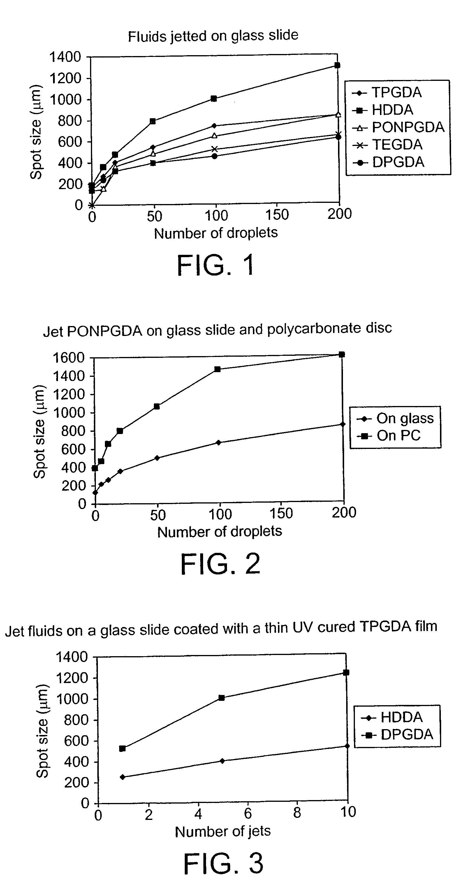
[0095]Each droplet had an in-flight diameter of approximately 50 μm. The number of droplets deposited on the spot was varied and the size of the spot (after spreading) was plotted against the number of droplets used to form the spot. The results for the jetting of various monomers onto a glass substrate are shown in FIG. 1.

[0096]As can be seen, the spot size increases with the number of droplets but not, however, as a linear relationship. The degree of increase is reduced as the number of droplets increases.

[0097]PONPGDA droplets were jetted onto the same target on a glass slide and a polycarbonate disc. The results are shown in FIG. 2.

[0098]As can be seen, the spot size of jet fluids on the polycarbonate substrate is much larger than that on the glass slide, because PONPGDA ...

example 3

[0099]Three fluids: PONPGDA, DPGDA and HDDA were jetted at room temperature onto the same target area of a glass slide coated with a thin film of UV-cured TPGDA. Of the three fluids, the surface tension of PONPGDA is lowest and is lower than that of the substrate TPGDA film. The spot size of PONPGDA is very large and a ring is formed, making it difficult to form a continuous film. The results from the other two fluids are shown in FIG. 3.

[0100]Thus it can be seen:

[0101]Jetting a fluid (PONPGDA) whose surface tension is lower than that of substrate leads to poor film formation.

[0102]Fluid (HDDA) with higher surface tension than the substrate-forms a smaller spot size, which is not favourable to make very thin films.

[0103]Large spot size and good film formation is obtained from DPGDA which possesses approximately the same value of surface tension as the substrate (TPGDA).


PUM

PropertyMeasurementUnit
thicknessaaaaaaaaaa
thicknessaaaaaaaaaa
thicknessaaaaaaaaaa

Abstract

A method is described of producing thin layers (below 10 μm in thickness) by directing droplets (preferably by inkjet printing techniques) onto precise locations on a substrate, the liquid of the droplets having a viscosity such that the droplets, on impact with the substrate, spread out to form relics on the substrate that are at least 1.4 times the diameter of the droplets in flight, adjacent droplets merging to form a continuous layer on the substrate. The droplets may have different compositions to form images within the layer. Successive layers may be added to built up a three dimensional structure whose properties can be tailored by the compositions used to build up a composite.

Description

TECHNICAL FIELD[0001]The present invention relates to production of films composed of thin layers using ink jet processes, that is to say layers with a thickness below 10 μm, more preferably less than 5 μm, especially 1 to 2 μm and it is contemplated making layers thinner than 0.1 μm. The term “layer” is intended to cover a single thickness of deposited material that forms, or is one of several layers that form, a film and the term “film” is intended to cover both free-standing films and films supported on a substrate.BACKGROUND ART[0002]It is known from the prior art to apply thin layers and films to a substrate using many techniques, for example printing and screen-printing. Inkjet and laser printers will also produce thin films of ink.[0003]It is known to use jet printing techniques to form three dimensional objects; for example in U.S. Pat. Nos. 5,059,226 and 5,140,937 there is disclosed the direct jetting of curable materials onto a substrate. In WO 97 / 48557 and WO 99 / 19900, th...

Claims


Application Information

Patent Timeline
Patent Type & Authority Patents(United States)
IPC IPC(8): B05C5/00B05D1/02B05D1/36B05D1/38B05D3/06B05D1/26B05D7/24B29C67/00
CPCB29C67/0055B29C67/0059B42D25/29B42D25/00B42D2033/20B42D2033/24B42D25/328B42D25/324B42D2033/46B29C64/112B33Y70/00B33Y10/00B29C64/106B42D25/333
Inventor MATSUMOTO, YONETATSUSTUDER, PEGGY DIANEZHAO, YONGBARNY, STEFANPATEL, RANJANA CHANGANBHAI
Owner HUNTSMAN ADVANCED MATERIALS AMERICAS INC
Learn More