System and method for improving lidar data fidelity using pixel-aligned lidar/electro-optic data

a lidar/electro-optic data and pixel-aligned technology, applied in the field of three-dimensional modeling, can solve the problems of limiting the maximum spatial resolution of range data, and range scanners may not be able to discern surface details of objects

Active Publication Date: 2008-08-26
UTAH STATE UNIVERSITY
View PDF1 Cites 50 Cited by
  • Summary
  • Abstract
  • Description
  • Claims
  • Application Information

AI Technical Summary

Problems solved by technology

Physical limitations of the range scanner constrain the maximum spatial resolution of the range data, which decreases with distance from the range scanner.
At large distances, the range scanner may not be able to discern surface details of an object.

Method used


Image

  • System and method for improving lidar data fidelity using pixel-aligned lidar/electro-optic data
  • System and method for improving lidar data fidelity using pixel-aligned lidar/electro-optic data
  • System and method for improving lidar data fidelity using pixel-aligned lidar/electro-optic data

Examples


Embodiment Construction

[0011]The presently preferred embodiments of the present invention will be best understood by reference to the drawings, wherein like parts are designated by like numerals throughout. It will be readily understood that the components of the present invention, as generally described and illustrated in the figures herein, could be arranged and designed in a wide variety of different configurations. Thus, the following more detailed description of the embodiments of the apparatus, system, and method of the present invention, as represented in FIGS. 1 through 6, is not intended to limit the scope of the invention, as claimed, but is merely representative of presently preferred embodiments of the invention.

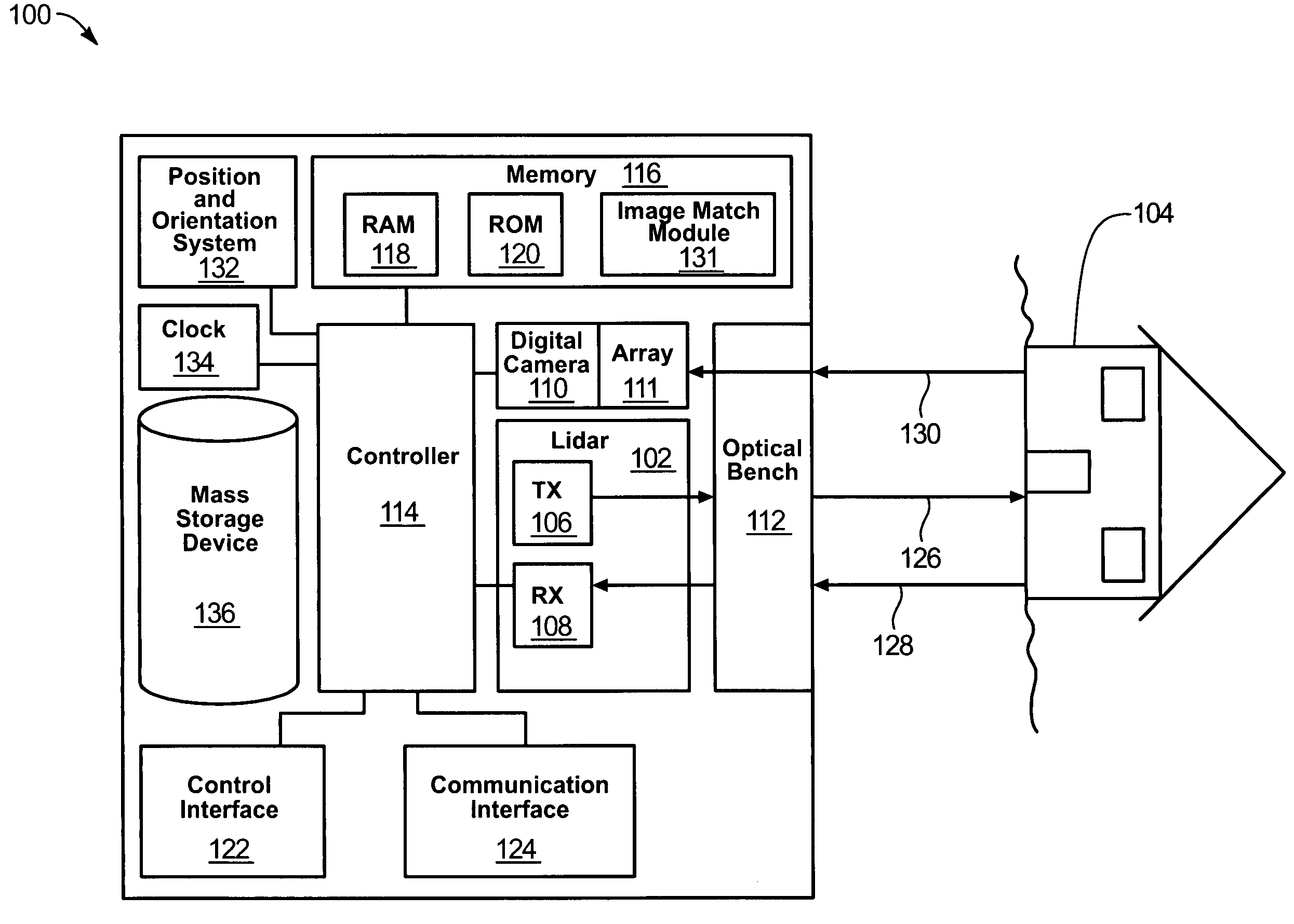
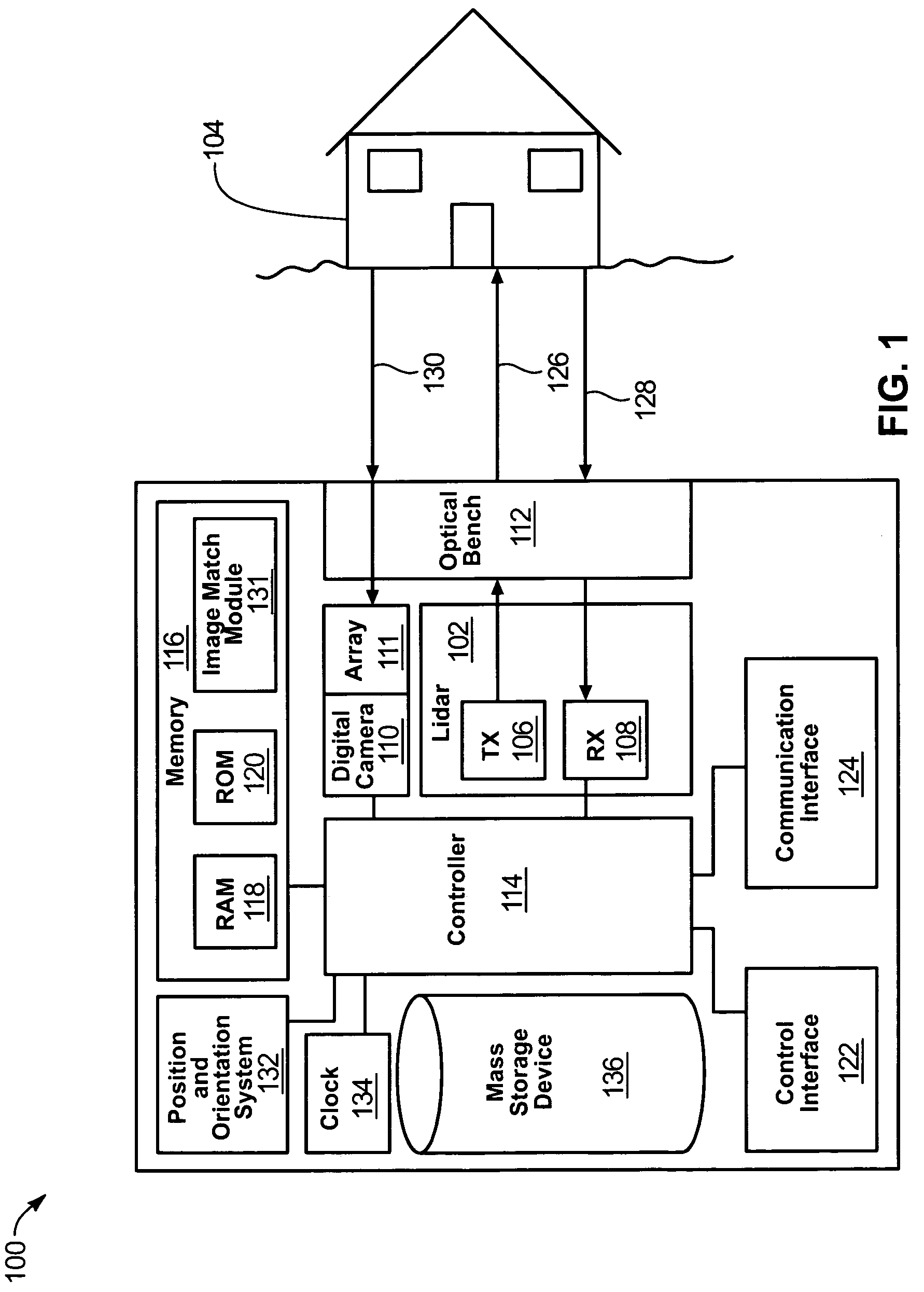
[0012]Referring to FIG. 1, a block diagram of an image capture system 100 is shown. The system includes a lidar 102 for scanning an object 104 to generate range data, i.e., distance measurements from the lidar 102 to real-world objects. The object 104 may be any indoor or outdoor three...


PUM


Abstract

A lidar and digital camera system collect data and generate a three-dimensional image. A lidar generates a laser beam to form a lidar shot and to receive a reflected laser beam to provide range data. A digital camera includes an array of pixels to receive optical radiation and provide electro-optical data. An optical bench passes the laser beam, reflected laser beam, and optical radiation and is positioned to align each pixel to known positions within the lidar shot. Pixels are matched to form a lidar point-cloud which is used to generate an image.

Description

TECHNICAL FIELD[0001]The present invention relates to three-dimensional modeling. More specifically, the present invention relates to a system and method that incorporates a lidar to perform three-dimensional imagery in real time.BACKGROUND OF THE INVENTION[0002]Lidar (light detection and ranging) uses laser technology to make precise distance measurements over long or short distances. One application of lidar is the range scanner, or scanning lidar. Lidar transceivers operate on the principle of transmitting laser light that then reflects off of a given object and returns to a lidar receiver. The distance to an object is then determined by analyzing the laser signal through various techniques. During the scanning process, the lidar makes repeated range measurements to objects in its path. Through repeated measurements of an object by individual laser transmissions, the shape of the object can be determined. The resulting range data is collected and serves as a rough model of the sc...

Claims


Application Information

Patent Timeline
Patent Type & Authority Patents(United States)
IPC IPC(8): G01C3/06
CPCG01C7/04G01S17/023G01S17/89G01S17/08G01S17/87G01S17/86
Inventor PACK, ROBERT TAYLORBUDGE, SCOTT EZRA
Owner UTAH STATE UNIVERSITY
Why Eureka
Try Eureka