Floor structure

a floor structure and floor technology, applied in the direction of bridges, bridge structural details, flooring, etc., can solve the problems of large dismantling operation, large amount of dismantling expense, and no consideration at all given to a unit structure, so as to prevent displacement and reduce costs

Inactive Publication Date: 2008-09-02
ASAHI ENG CO LTD +1
View PDF26 Cites 11 Cited by
  • Summary
  • Abstract
  • Description
  • Claims
  • Application Information

AI Technical Summary

Benefits of technology

[0021]The floor structure is effective to prevent displacement due to an active load when a floor structure is formed by arranging steel beams in parallel. The displacement preventing spacer is preliminarily prepared, and the displacement preventing spacer is fitted between the steel beams which are arranged in parallel. By doing so, the individual steel beams are effectively prevented from being displaced downward against the active load.
[0022]...

Problems solved by technology

However, the bridge shown in the above-mentioned Patent Document 1 is a structure in which the integration is achieved by the steel beams and the iron reinforced concrete placed at the site, and no consideration is given at all to a unit structure in which the steel beams are dismantled one by one and re-used.
Therefore, the conventional technique is not suited as a floor structure of a temporarily built bridge and the like.
At the time of rebuilding, a large scale dismantling operation and a large amount of dismantling expense are required.
Moreover, a great deal of scrap is produced thereby impairing the environment.
In addition, the form assembling process, the bar arranging process and the concrete placing process are required, thus resulting in increased construction cost.
On the other hand, in the above-mentioned roadbed structure, many heavy ...

Method used


Image

  • Floor structure
  • Floor structure
  • Floor structure

Examples


first embodiment

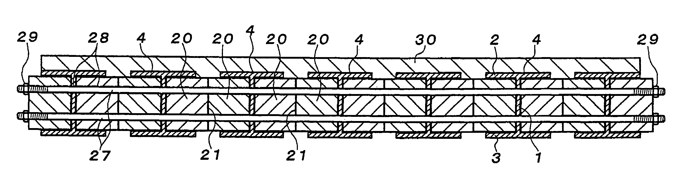
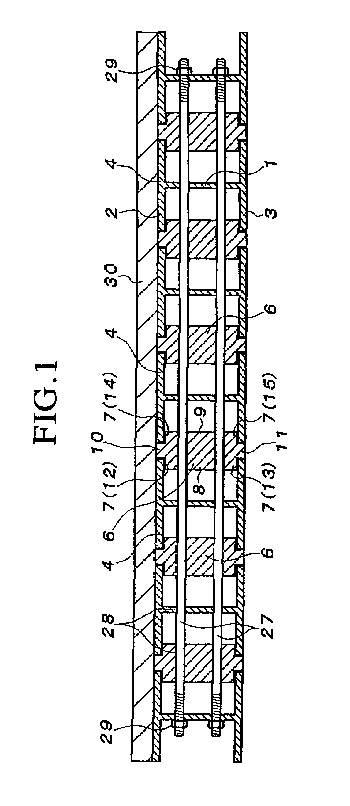
[0043]As its first embodiment, as shown in FIG. 1, the floor structure further comprises displacement preventing spacers 6 interposed between the upper flanges 2 and the lower flanges 3 of the adjacent steel beams 4. Each of the displacement preventing spacers 6 includes a left fitting part 8 fitted between the upper and lower flanges 2, 3 of the adjacent left side steel beam 4, a right fitting part 9 fitted between the upper and lower flanges 2, 3 of the adjacent right side steel beam 4, an upper interposing part 10 interposed between the upper flanges 2 of the adjacent steel beams 4, and a lower interposing part 11 interposed between the adjacent lower flanges 3.

[0044]A left side upper step part 12 formed at an interlocking part between the upper interposing part 10 and the left fitting part 8 is engaged with a lower surface of the upper flange 2 of the left side steel beam 4 and a left side lower step part 13 formed at an interlocking part between the upper interposing part 10 an...

second embodiment

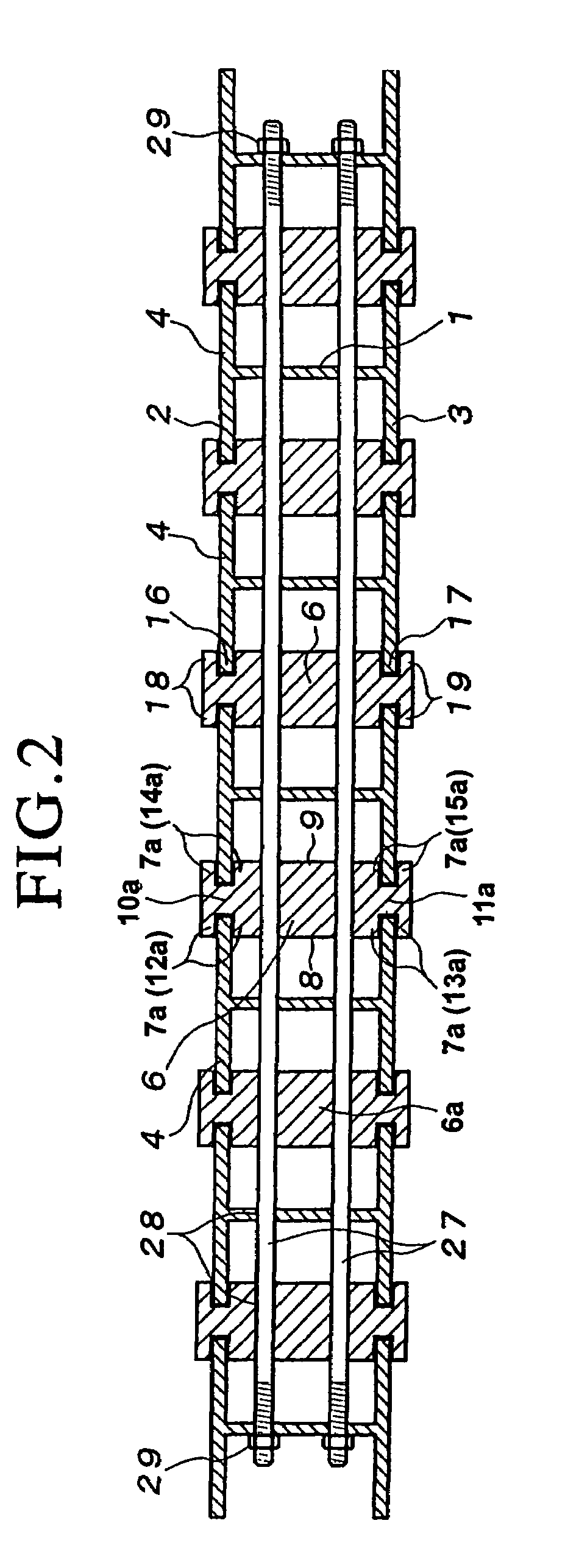
[0046]As a second embodiment, as shown in FIG. 2, the displacement preventing spacer 6a is provided at an upper end of the upper interposing part 10a with an upper engagement part 18 which is engaged with upper surfaces of the upper flanges 2 of the adjacent steel beams 4, and the displacement preventing spacer 6a is provided at a lower end of the lower interposing part 11a with a lower engagement part 19 which is engaged with lower surfaces of the lower flanges 3 of the adjacent steel beams 4.

[0047]That is, the displacement preventing spacer 6a is provided at the left and right of the upper interposing part 10a with upper engagement grooves 16. The upper flanges 2 of the adjacent steel beams 4 are brought into engagement with the left and right upper engagement grooves 16, thereby restraining the upper flanges 2. Thus, the load receiving part 7a is formed by the pair of upper step parts 12a, 14a which define the left and right upper engagement grooves 16.

[0048]Likewise, the displac...

third embodiment

[0049]As a third embodiment, as shown in FIG. 3, each displacement preventing spacer is separated into an upper displacement preventing spacer 6′ interposed between the upper flanges 2 of the adjacent steel beams 4, and a lower displacement preventing spacer 6″ interposed between the lower flanges 3 of the adjacent steel beams 4 (namely, the spacer is formed of separate members). The load receiving parts 7′ of the respective displacement preventing spacers 6′, 6″ are brought into engagement with the adjacent upper flanges 2 and the adjacent lower flanges 3 to receive the active load incurred by the individual steel beams 4, so that the individual steel beams 4 are inhibited from displacing downward. That is, the load incurred by the individual steel beams 4 is incurred by the adjacent steel beams 4 through the displacement spacers 6′, 6″ and the load is dispersed to the entire structure.

[0050]More specifically, as shown in FIG. 3, upper engagement grooves 16′ are formed at the left ...


PUM

PropertyMeasurementUnit
Widthaaaaaaaaaa
Surface pressureaaaaaaaaaa
Displacementaaaaaaaaaa

Abstract

A floor structure comprises a plurality of steel beams 4 arranged in parallel, each steel beam 4 including a web, an upper flange disposed at an upper end of the web, and a lower flange disposed at a lower end of the web, a floor surface being formed on the upper flange 2. The floor structure further includes displacement preventing spacers interposed between the upper flanges and/or lower flanges of the adjacent steel beams. Each displacement preventing spacer includes a load receiving part which is brought into engagement with the adjacent upper flanges and/or lower flanges to receive an active load incurred by the individual steel beams 4 so as to inhibit the steel beams 4 from displacing downward.

Description

[0001]This application is a divisional application of application Ser. No. 10 / 854,186, filed May 27, 2004 now U.S. Pat. No. 7,373,760.BACKGROUND OF THE INVENTION[0002]1. Field of the Invention[0003]The present invention relates to a floor structure such as a floor plate bridge structure built on a river or land, a slab structure of respective hierarchies such as a steel frame building and an iron reinforced concrete building, a roadbed structure formed on an upper surface of an underground construction, a roadbed structure laid on a ground surface, or the like.[0004]2. Related Art[0005]Patent Document 1 shows a bridge structure, in which steel beams each consisting of an upper flange, a lower flange and a web are arranged in parallel, an iron reinforcement is arranged and concrete is placed between the adjacent steel stocks, i.e., in a space defined by upper and lower flanges of the adjacent steel beams and the web, and the iron reinforced concrete and the web are tightly connected ...

Claims


Application Information

Patent Timeline
IPC IPC(8): E04C5/08E04C2/42E01D19/12E01D15/133E01D2/00E01D2/02E01D15/12E01D101/40E04B5/02E04B5/10E04C3/292
CPCE01D19/125E04C3/292E04B5/10E01D2101/30
Inventor TOKUNO, MITSUHIROTSUDA, KAZUTOSHISAITO, FUMIHIRO
Owner ASAHI ENG CO LTD
Why Eureka
Try Eureka