Wind turbine with hydraulic transmission

a technology of hydraulic transmission and wind turbine, which is applied in the direction of gearing control, motors, engine fuctions, etc., can solve the problems of significant mechanical inefficiency of wind turbine operation, low wind turbine speed, and high price of variable pitch rotors and braking mechanisms, etc., and achieve the effect of wind turbine speed reduction

Inactive Publication Date: 2008-09-02
MACKAY GARY
View PDF10 Cites 111 Cited by
  • Summary
  • Abstract
  • Description
  • Claims
  • Application Information

AI Technical Summary

Benefits of technology

[0012]The inventors have discovered that a closed loop hydraulic system which may effectively deal with an “overrunning” load condition, in other words having dynamic braking capability, may successfully be applied to a wind turbine to provide efficient transmission of energy from the turbine rotor to the generator. An induction motor may typically absorb more horsepower as a generator than it develops as a motor.
[0014]The applicants have found that a low-speed, high torque hydraulic motor driven by the wind turbine rotor at a low speed to create an overrunning load condition, may efficiently drive such a hydraulic system as a hydraulic pump. The motor acting as a pump is preferably directly driven by the rotor, without any speed increasing gears. Similarly, a variable displacement pump which is driven by the overrunning load to reverse its function may be effectively used to drive the electrical generator.

Problems solved by technology

It is a continuing problem with wind-driven turbines to provide a cost-effective method of smoothing the torque generated by the rotor so as to reduce torque fluctuations in the drivetrain to the generator.
However, such transmissions, variable pitch rotors and braking mechanisms are expensive, prone to mechanical breakdown and introduce a significant source of mechanical inefficiency to the wind turbine operation.
Although it is generally advantageous to reduce the tower load, this arrangement necessitates long hydraulic fluid hoses to and from the hydraulic pump, which is disadvantageous.
However, a closed-loop system has not been attempted because of the difficulty in dealing with overspeed situations.
In a closed loop system, hydraulic resistance to the increased torque would result in intolerable heat buildup in the system, if fluid pressure is not controlled.
This energy dissipation generates tremendous amounts of heat and active cooling or heat exchanging is necessary.
In response to high pressure caused by high wind and rotor speeds, the displacement of the hydraulic motor decreases, further increasing system pressure.

Method used


Image

  • Wind turbine with hydraulic transmission
  • Wind turbine with hydraulic transmission
  • Wind turbine with hydraulic transmission

Examples


Embodiment Construction

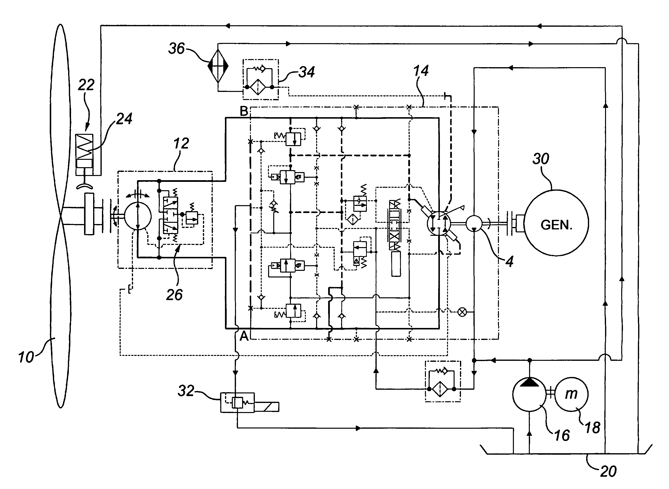
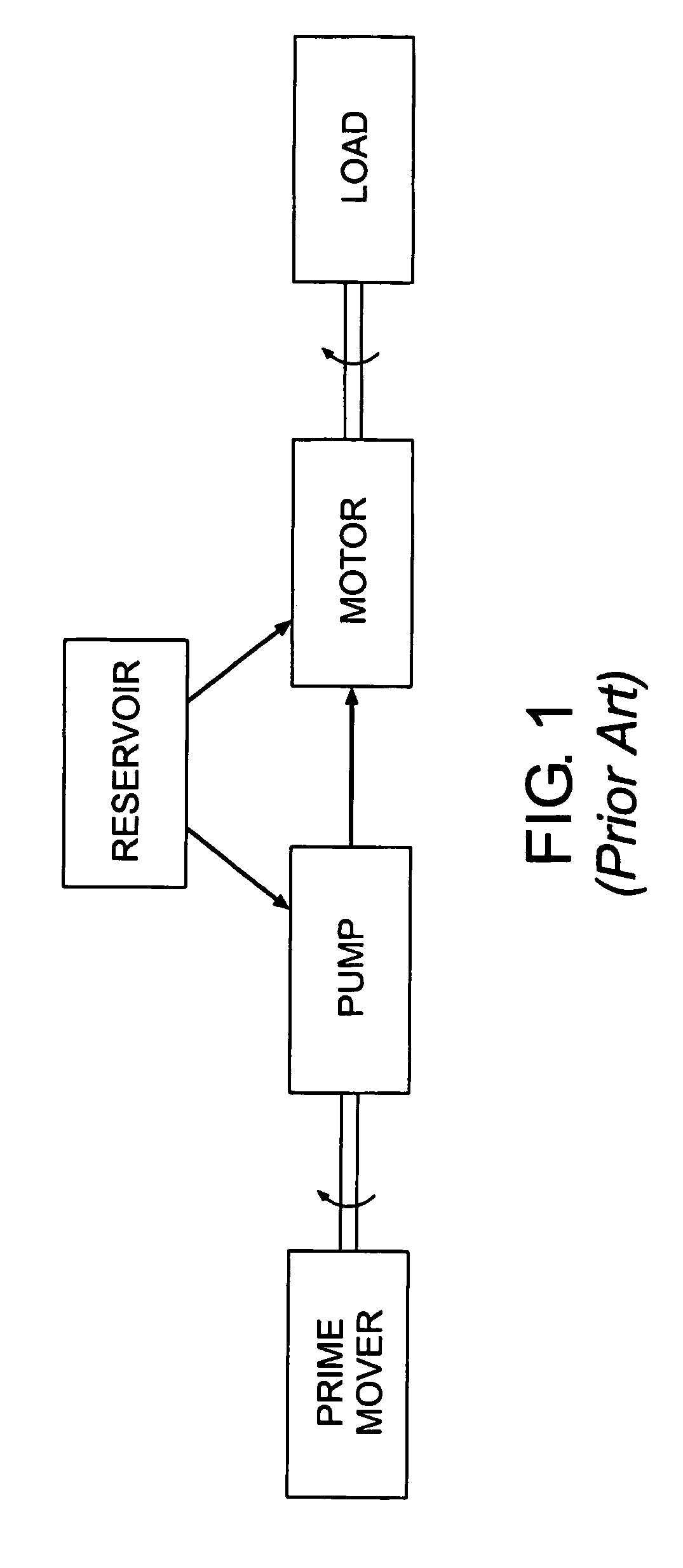
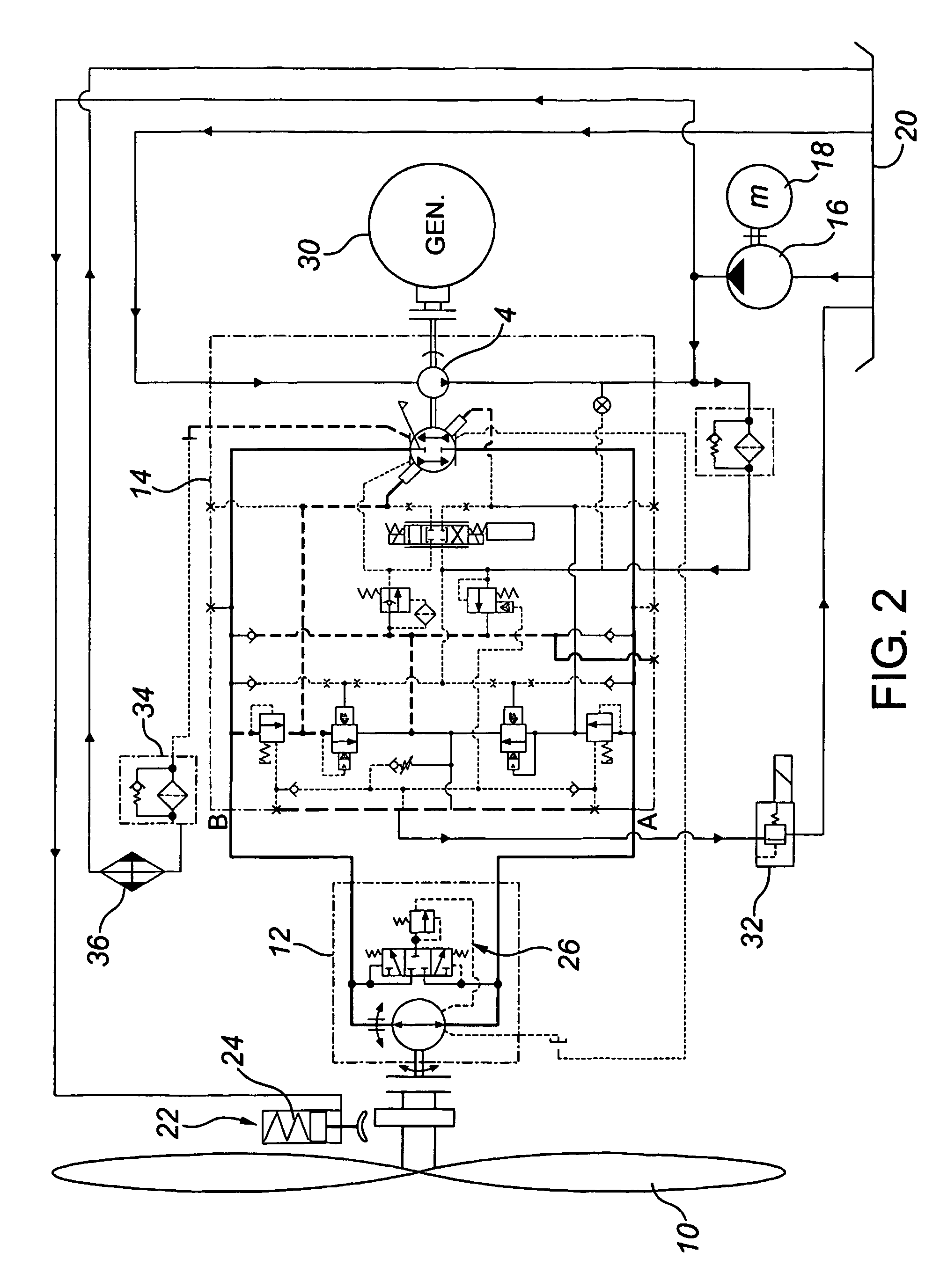
[0039]The present invention provides for a wind turbine having a closed loop hydraulic system to transfer torque from the wind-driven rotor to a generator. When describing the present invention, all terms not defined herein have their common art-recognized meanings. As used herein, a “closed loop” hydraulic system is equivalent to a closed circuit hydraulic system and refers to a hydraulic system where a substantial portion of the hydraulic fluid returns directly to the hydraulic pump after passing through the hydraulic motor. In a closed loop system, the hydraulic fluid does not return to an open fluid reservoir or tank but rather flows in a complete path from the pump, through a conductor to the motor and back to the pump. As used herein, “hydraulic oil” of “oil” refers to any suitable hydraulic fluid as is well known in the art.

[0040]The present invention incorporates principles of hydraulic power transmission and control systems for hydraulic power transmission systems. A person...


PUM


Abstract

A wind turbine includes a closed loop hydrostatic transmission. The rotor is directly coupled to a low-speed high torque hydraulic motor, which is pressure-reversible to act as a pump. A variable displacement, pressure compensated hydrostatic transmission receives the hydraulic fluid output and drives a generator. The hydrostatic transmission and the generator may be compactly located in the nacelle of wind turbine tower.

Description

CROSS-REFERENCE TO RELATED APPLICATION[0001]This application claims the priority benefit of U.S. Provisional Application No. 60 / 319,249 filed on May 16, 2002 and entitled Wind Turbine with Hydrostatic Transmission, the contents of which are incorporated herein by reference.FIELD OF THE INVENTION[0002]The present invention relates to wind turbines for electricity generation.BACKGROUND OF THE INVENTION[0003]Wind turbines use wind energy to generate electricity. A conventional wind turbine includes a rotor mounted on a tower. The rotor may turn up to about 60 rpm in a steady wind of about 20 mph and connect to an alternator / generator through a speed increasing transmission. Typical generators include synchronous or asynchronous generators and require a constant input shaft speed of about 1200 or 1800 rpm, depending on the type of generator, to produce quality power. Although variable speed generators are available, the power output of a variable speed generator must be conditioned befo...

Claims


Application Information

Patent Timeline
Patent Type & Authority Patents(United States)
IPC IPC(8): F03D11/02F03D9/00F16H61/42
CPCF03D7/02F03D7/043F03D11/02F04B17/02F16H61/421F16H61/431F05B2220/70642F05B2220/70644Y02E10/725F05B2270/1033Y02E10/722Y02E10/723F05B2260/406F03D15/00F03D9/255F03D9/28Y02E10/72
Inventor HARVEY, ALEXANDER S.MCCONNELL, DAVID
Owner MACKAY GARY
Why Eureka
Try Eureka