
Universal tubing hanger suspension assembly and well completion system and method of using same

a technology of universal tubing and suspension assembly, which is applied in the direction of sealing/packing, drilling pipes, and wellbore/well accessories, etc., can solve the problems of not being able to connect the christmas tree to the manufacturer's housing, unfavorable safety, and substantial amount of engineering and cost or additional equipmen

Active Publication Date: 2008-09-02
DRIL QUIP +1
View PDF42 Cites 49 Cited by
  • Summary
  • Abstract
  • Description
  • Claims
  • Application Information

AI Technical Summary

Benefits of technology

This solution enables cost-effective and efficient well completion by eliminating the need for proprietary-specific designs, reducing engineering costs, and allowing for the use of off-the-shelf components, thereby simplifying the installation process and reducing the overall cost of subsea well completion.

Problems solved by technology

The locking mechanism ensures that any subsequent pressure from within the well acting on the tubing hanger will not cause the tubing hanger to lift from the wellhead housing thereby resulting in an unsafe condition.
There are a limited number of subsea wellhead equipment manufacturers worldwide.
Quite frequently, a well is completed on Manufacturer A's wellhead housing and casing hangers using a tubing hanger and / or Christmas tree from Manufacturer B. However, since Manufacturer A's housing and casing hanger design is proprietary, Manufacturer B may not be able to connect its Christmas tree to Manufacturer A's housing without a license from Manufacturer A at a fee in order to design Manufacturer B's equipment to properly interconnect and mate with Manufacturer A's wellhead housing and casing hanger.
This results in a substantial amount of additional engineering and costs or additional equipment (such as a tubing spool) when electing to purchase Manufacturer B's equipment for use with Manufacturer A's wellhead housing.
Since each wellhead housing / system manufacturer has multiple models of housings and casing hangers with different proprietary details, it is not practical or economical for other manufacturers to build up an inventory of equipment for installation on other manufacturers' wellhead equipment.
In addition to the added costs, it also increases the delivery time which is often vitally important to the well owner.

Method used


Image

  • Universal tubing hanger suspension assembly and well completion system and method of using same
  • Universal tubing hanger suspension assembly and well completion system and method of using same
  • Universal tubing hanger suspension assembly and well completion system and method of using same

Examples


Embodiment Construction

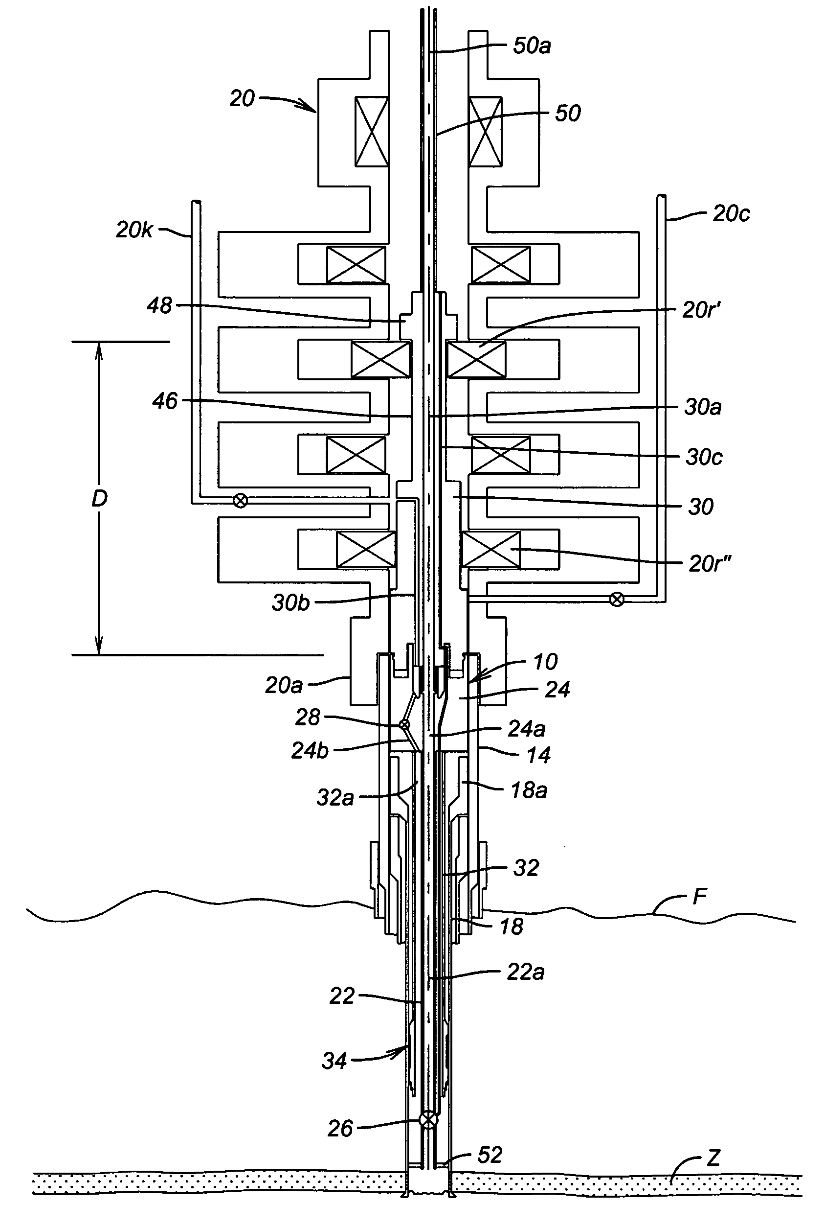
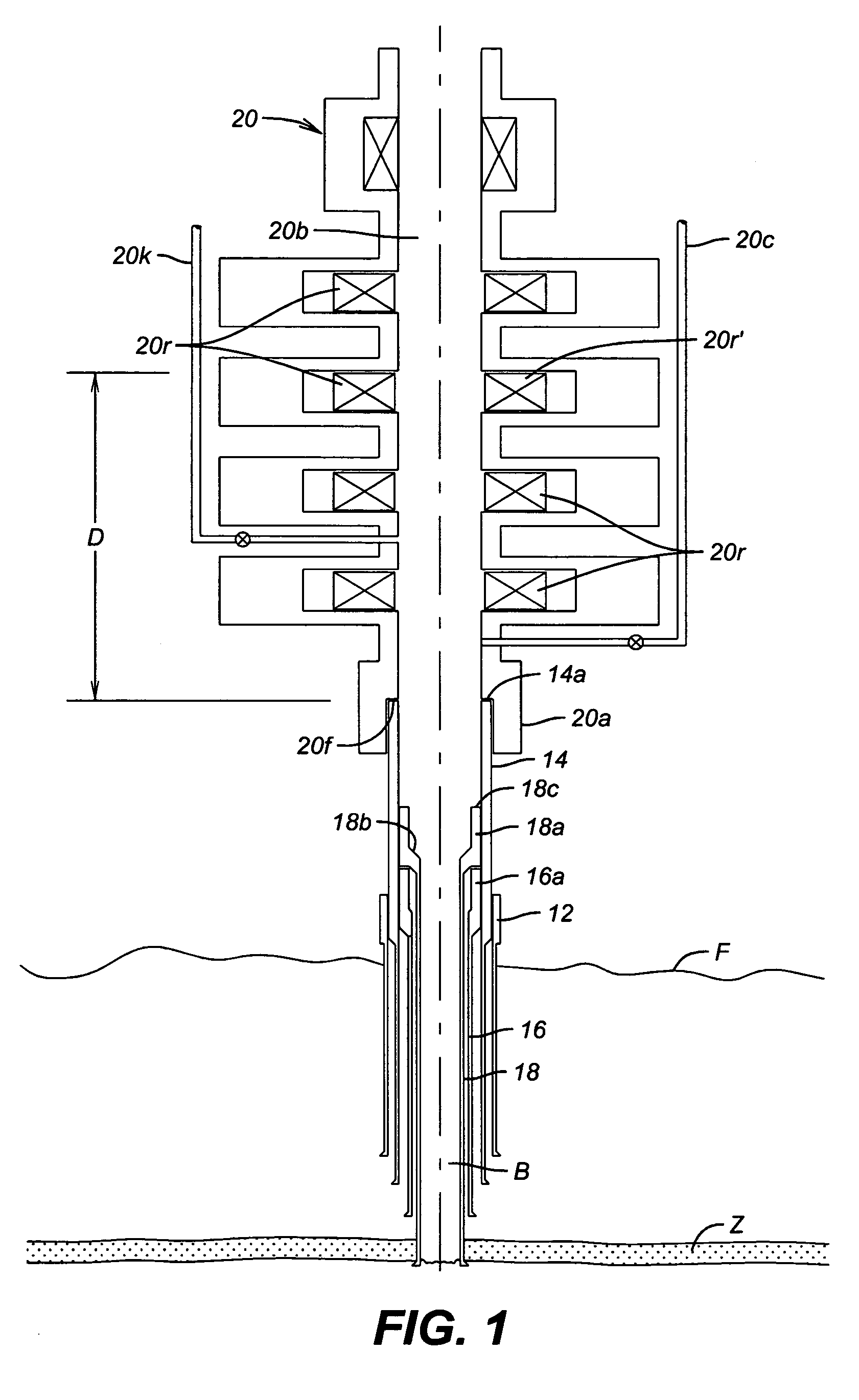
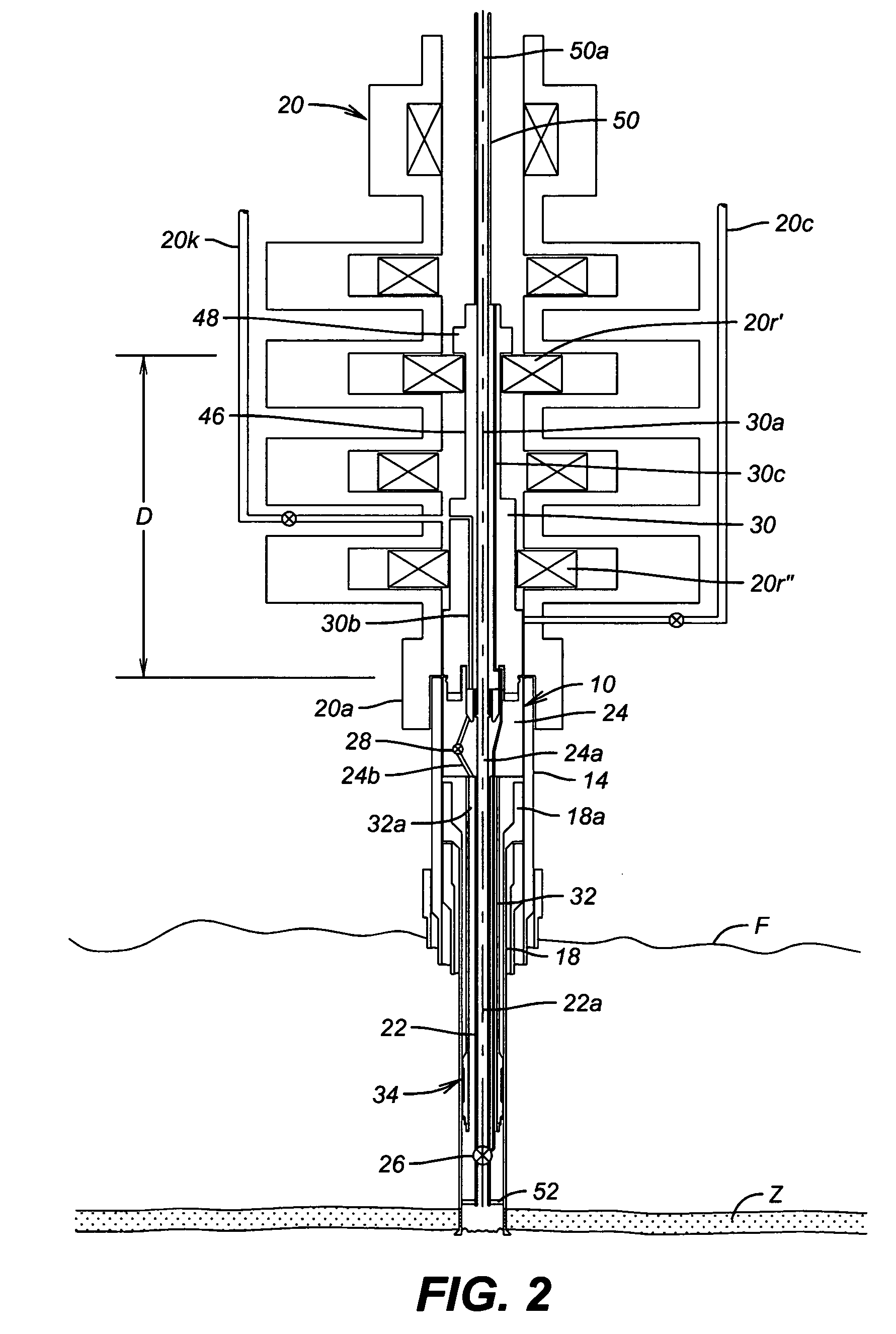
[0025]An embodiment of the invention is described in detail with specific reference to the drawings. This invention concerns completion of a well that has been drilled and which has its bore hole lined with casing. Referring to FIG. 1, a typical drilled well bore B is shown extending from the sea floor F down to a zone Z, typically communicating with a reservoir of hydrocarbon fluids. The well bore B is shown having a series of tubular strings of casing pipe extending from the sea floor F down into the bore B as is well known in the art. The series of pipe strings, beginning from the outermost string, includes a conductor housing 12, a wellhead housing 14, a first or outer casing string 16 with hanger 16a, and an inner or production casing string 18 with hanger 18a. It is to be understood that the well depicted in FIG. 1 is merely representative of a typical well for purposes of illustrating the present invention, and thus the present invention is not limited to wells of this precis...


PUM


Abstract

A tubing hanger suspension assembly for an oil and gas well completion system and a method of installing same. The tubing hanger suspension assembly includes a tubing hanger housing which is positioned in the wellhead housing. The tubing hanger assembly includes a sealing and lockdown mechanism capable of providing sealing and load support of the production tubing in the production casing string. A stab sub assembly connected to the upper end of the tubing hanger suspension assembly and lower end of the Christmas tree assembly provides downhole hydraulic and electric functionality and annulus access to the production tubing.

Description

CROSS-REFERENCE TO RELATED APPLICATIONS[0001]This application claims priority to U.S. Provisional Application Ser. No. 60 / 682,250, filed May 18, 2005, which is hereby incorporated by reference in its entirety.BACKGROUND OF THE INVENTION[0002]1. Field of the Invention[0003]The present invention relates to a subsea wellhead assembly for an oil and gas well, and more particularly relates to a universal tubing hanger suspension assembly for use in a subsea wellhead assembly.[0004]2. Description of the Related Art[0005]A typical subsea wellhead assembly includes a wellhead housing installed at the sea floor. With a drilling blowout preventer (BOP) stack installed on the wellhead housing, the well bore is drilled while successively installing concentric casing strings in the well bore. Typically, each successive casing string is cemented at its lower end and includes a casing hanger sealed with a mechanical seal assembly at its upper end in the wellhead housing.[0006]In order to produce t...

Claims


Application Information

Patent Timeline
Patent Type & Authority Patents(United States)
IPC IPC(8): E21B23/03
CPCE21B23/01E21B33/043E21B33/0422E21B33/04
Inventor BROUSSARD, EARL
Owner DRIL QUIP
Learn More