Working machine

a technology of working machine and working shaft, which is applied in the direction of soil shifting machine/dredger, roof, transportation and packaging, etc., can solve the problems of low reliability of pipeline protection, increased cost, and prone to damage or breakage, so as to prevent pipeline damage or breakage, protect pipeline, and ensure the effect of safety

Active Publication Date: 2008-09-02
KOBELCO CONSTR MASCH CO LTD
View PDF5 Cites 9 Cited by
  • Summary
  • Abstract
  • Description
  • Claims
  • Application Information

AI Technical Summary

Benefits of technology

[0010]Accordingly, it is an object of the present invention to provide a working machine which can reliably protect a pipeline connected to front and back hydraulic devices through a side deck, which can eliminate the problem of the strength of the side deck being reduced, which simplifies pipework, and which is advantageous in terms of costs.
[0013]According to the present invention, a reinforcing member including a piping frame which has a space for accommodating the pipeline and which serves as a reinforcing member is disposed in a front-back direction at an outermost side of a side deck in a widthwise direction where the pipeline is installed, and the pipeline is passed through the reinforcing member. Therefore, the piping frame receives an upward pushing force or a sideways shock and reliably protects the pipeline. Consequently, it is possible to prevent the pipeline from becoming damaged or from breaking.
[0014]In addition, it is desirable for the reinforcing member, required to provide the side deck with sufficient strength and rigidity, to have a structure allowing it to serve as a piping frame. In this case, since it is not necessary to additionally use a special-purpose duct (or a protective cover), it is possible to reduce costs and to overcome the problem of the strength of the side deck being reduced when a piping through hole is formed in the side deck.
[0015]Since, it is only necessary to pass the pipeline through the piping frame, unlike the related art, additional operations, such as securing the pipeline to the inner surface of a decorative cover, are not required, thereby facilitating pipework.

Problems solved by technology

In the former method of passing the pipeline below the side deck, since the pipeline is directly pushed by an upward force from below by, for example, soil and stones, it tends to be damaged or to break.
However, since the protective cover, itself, may be damaged by an upward pushing force from below it, the reliability with which the pipeline is protected is low.
Therefore, costs are increased.
In the latter technology, since the pipeline is covered with a decorative cover which has a greater tendency to come into contact with obstacles than the protective cover and which has low strength / rigidity, the pipeline is not sufficiently protected.
In addition, since the pipeline must be secured to the inner surface of the decorative cover, the pipework becomes troublesome.

Method used


Image

  • Working machine
  • Working machine
  • Working machine

Examples


Embodiment Construction

[0023]An embodiment of the present invention will be described with reference to FIGS. 1 to 7.

[0024]In the description below, a hydraulic excavator will be taken as an example to which the present invention is applied.

[0025]Here, a mini-excavator which is called an excavator with short tail swing radius is taken as an example of the hydraulic excavator. In the mini-excavator, an upper rotating body rotates within an excavator width.

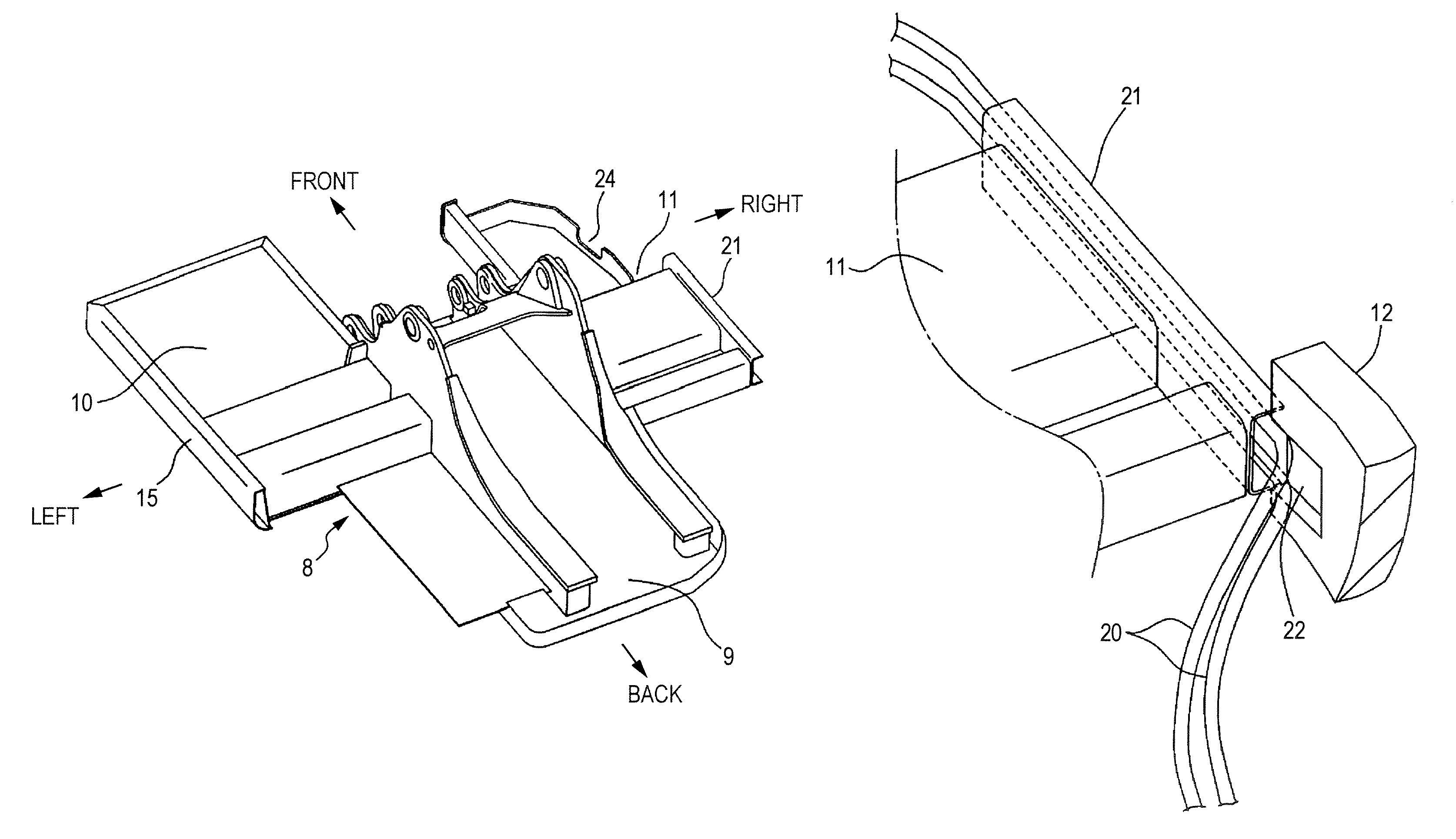
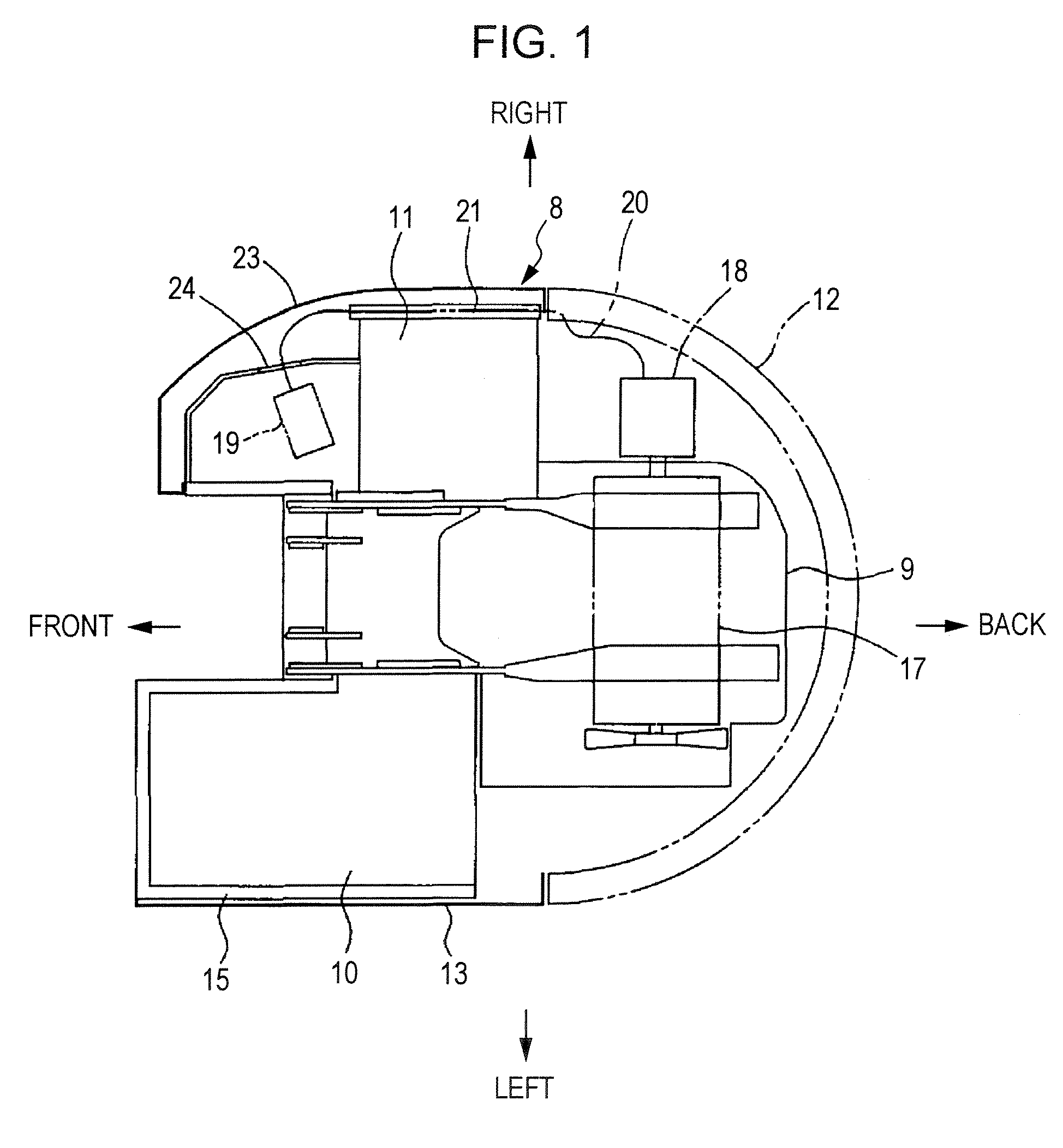
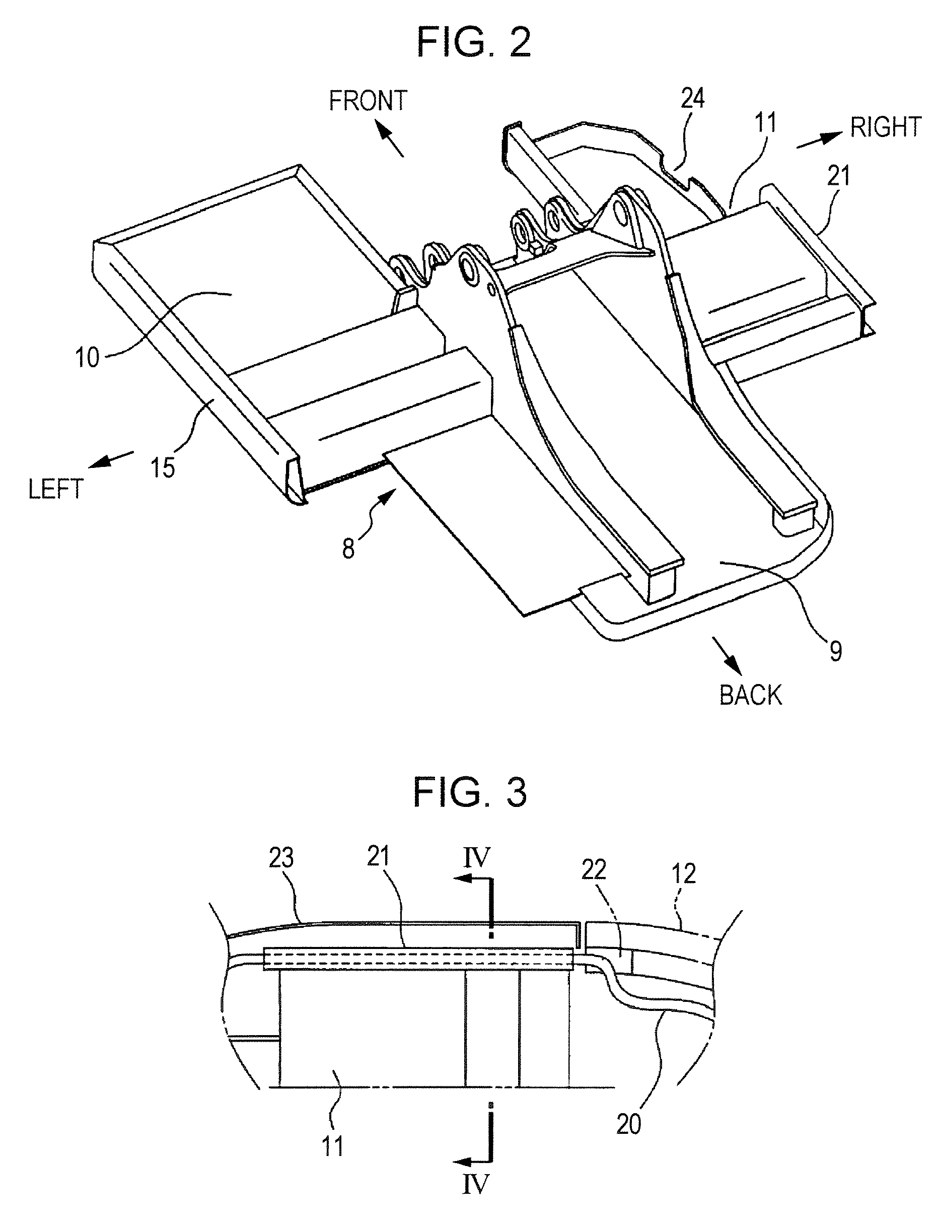
[0026]In FIGS. 6 and 7, reference numeral 1 denotes a crawler-type lower traveling body, and reference numeral 2 denotes an upper rotating body rotatably mounted on the lower traveling body 1. A working attachment (excavating device) 6 including a boom 3, an arm 4, and a bucket 5 is mounted to a front portion of the upper rotating body 2, and a cabin 7 is disposed at a left front portion of the upper rotating body 2.

[0027]FIG. 1 is a schematic plan view of an upper frame 8 serving as the body of the upper rotating body 2. Here, for the sake of simplifying...


PUM


Abstract

A working machine includes a pipeline disposed along a side deck in a front-back direction and connecting a hydraulic pump and a control valve. The hydraulic pump is mounted at a back portion of an upper frame of an upper rotating body and the control valve is mounted at a front portion of the upper frame. In the working machine, a reinforcing member having a space for accommodating the pipeline is mounted in the front-back direction of the side deck to an outermost side of the side deck in a widthwise direction thereof. The pipeline is passed through the reinforcing member.

Description

BACKGROUND OF THE INVENTION[0001]1. Field of the Invention[0002]The present invention relates to a working machine in which an upper frame of an upper rotating body has a piping structure.[0003]2. Description of the Related Art[0004]In an upper frame of a hydraulic excavator, a pipeline connecting front and back hydraulic devices may be disposed in a front-back direction through left and right side decks.[0005]For example, when a hydraulic pump is disposed at a back portion of the frame and a main control valve for operating a hydraulic actuator is disposed at the side deck, an oil supply / discharge pipeline connecting the pump and the valve is disposed so as to pass below the side deck.[0006]Japanese Unexamined Patent Application Publication No. 11-200407 discloses a structure for installing a pipeline at an inner surface of a decorative cover which is disposed at an outer side of a side deck.[0007]In the former method of passing the pipeline below the side deck, since the pipeline ...

Claims


Application Information

Patent Timeline
Patent Type & Authority Patents(United States)
IPC IPC(8): E02F9/00E02F9/16
CPCE02F9/2275E02F9/0875
Inventor MURAKAMI, MASAAKIOCHI, TOMOHIKO
Owner KOBELCO CONSTR MASCH CO LTD
Why Eureka
Try Eureka