Ladder

a technology of ladders and fasteners, applied in ladders, building construction, construction, etc., can solve the problems of high manufacturing cost, easy breakdown of fasteners, and relatively short life, and achieve the effect of low safety performance and high manufacturing cos

Active Publication Date: 2011-01-20
NEW TEC INTEGRATION (XIAMEN) CO LTD
View PDF24 Cites 11 Cited by
  • Summary
  • Abstract
  • Description
  • Claims
  • Application Information

AI Technical Summary

Benefits of technology

[0005]The present invention provides a ladder, it overcomes the shortages of the background techniques which have a low safety performance and a high manufacturing cost.
[0012]In a preferred embodiment of the present invention, the outside of said outer sleeve is projecting disposed with a clamping jaw, which can restrict the rotation of said outer sleeve and be able to clamp in the connection slot.
[0016]Compared to the background techniques: firstly, the shearing force generated between the step and stile is not only supported by the fastener, but also supported by the friction force or clamping force between the outer sleeve and connection slot, so the supporting force and the shear resistance are relatively high; secondly, because the position restriction portion can prevent the inner sleeve from moving out, so the fastening of inner sleeve and stile can also fasten the step, the outer sleeve and stile simultaneously, it is convenient to connect and its connection strength is high, the strength of each part would not be eliminated because of the connection; thirdly, inferred from the secondly advantage, the connection slot disposed on the stile is able to connect the step unit firmly, and would not eliminate the supporting strength of stile, thereby the quantity of material used would not be increased; fourthly, because the end of step is designed as an enclosure opening, which forms the position restriction portion, so the enclosure opening would not only be able to firmly locate the inner sleeve, but also the manufacture process is convenient and timesaving, further the strength of the step would not be eliminated; fifthly, because the outer sleeve surrounds the enclosure opening of step, so it not only can support the step and bear the shearing force, but also can prevent the enclosure opening from expanding by tightly surrounding it, prevents the inner sleeve from pulling out because of the pulling of the fastener; sixthly, because a clamping jaw is projecting disposed outside of the outer sleeve, it can not only restrict the rotation of outer sleeve, but also can clamp in the connection slot, so a great amount of friction force or clamping force would be generated; seventhly, it further disposed with a plastic element which is interference fit inside the locating slot, so the strength of the friction force between the plastic element and the locating slot is great enough to bear the shearing force; eighthly, the fastener seat is disposed by the end of fixed plate, that is also the center of inner sleeve, so the connection is firm.

Problems solved by technology

The first mounting structure, which utilizes a fastener directly fastens the stile and step, said supporting structure has drawbacks as follows: the shearing force generated between the step and stile is only supported by the fastener, so the fastener is easy to breakdown, its life length is relatively short and its safety performance is relatively low.
In order to enhance the strength of the stile, it has to enlarge the cross section of the stile or use a solid stile, which will greatly increase the quantity of material used and the manufacturing cost.

Method used


Image

  • Ladder
  • Ladder
  • Ladder

Examples


Embodiment Construction

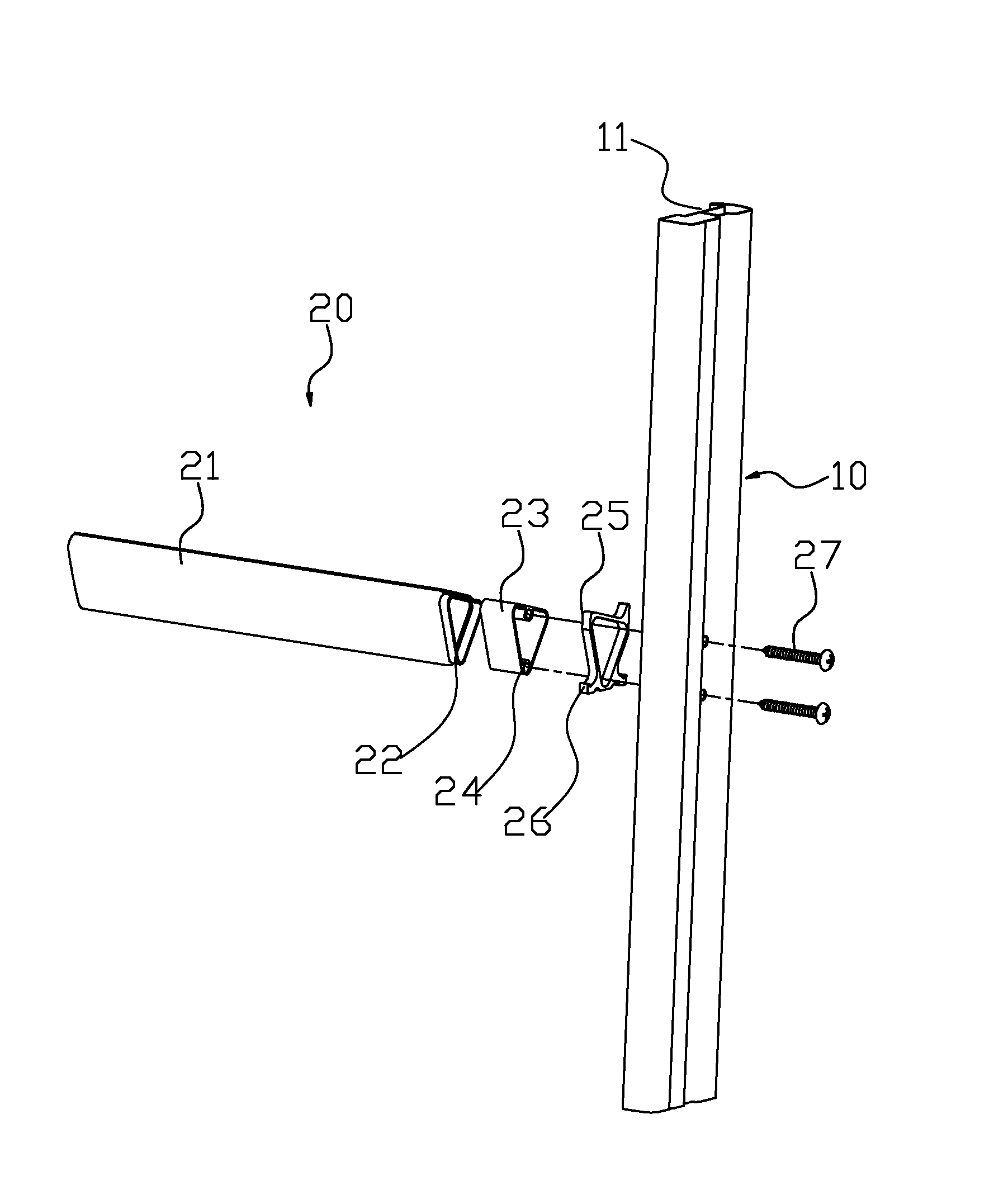
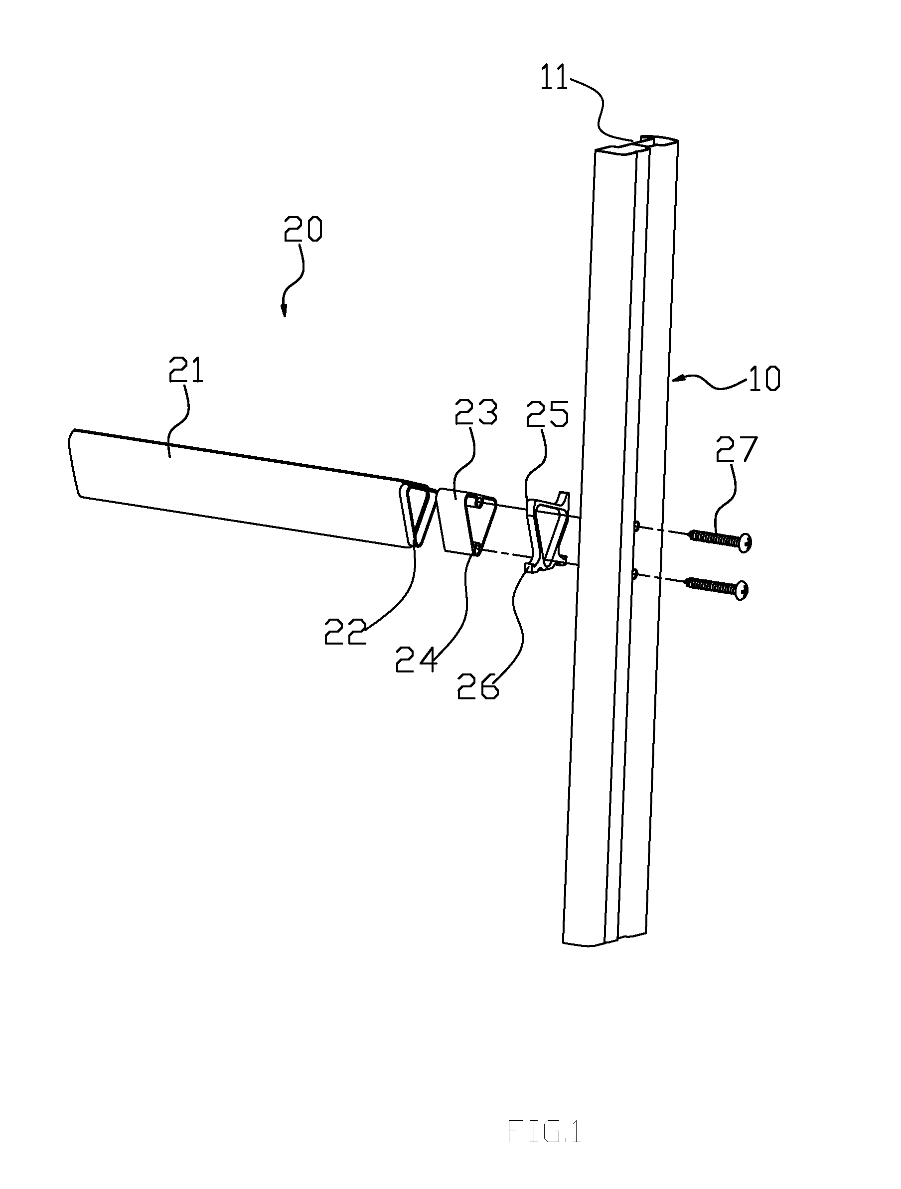
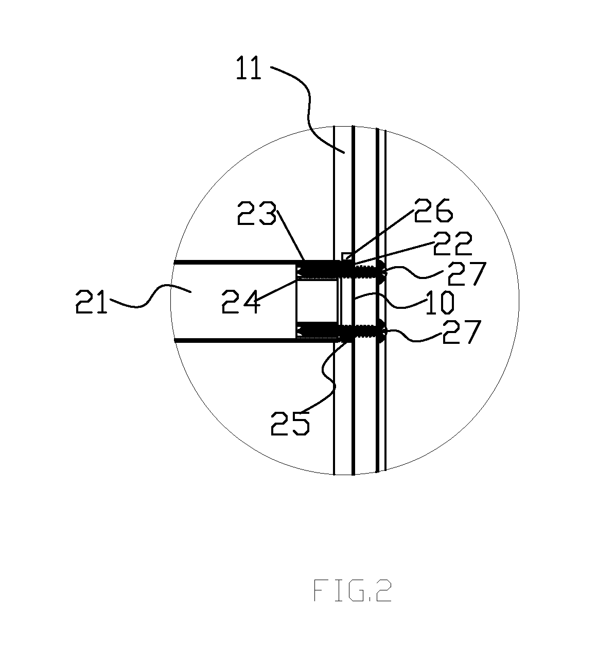
[0028]Please refer to FIG. 1 and FIG. 2, a ladder comprising two stiles 10 and a plurality of step units 20, said step units 20 are mounted between the two stiles 10.

[0029]Said stile is hollow, the cooperation surface (inner side surface) of the stile is longitudinally disposed with an inward concave connection slot 11, the inward concave design of said connection slot 11 can enhance the strength of stile 10.

[0030]Said step unit comprises a triangle hollow step 21, an inner sleeve 23 and an outer sleeve 25. Said inner sleeve 23 is fit into the hollow step 21; the end of said hollow step 21 is made as an enclosure opening 22, the inner circumferential edge of said enclosure opening 22 is smaller than the outer circumferential edge of inner sleeve 23, thereby said enclosure opening 22 can prevent the inner sleeve 23 from moving out of hollow step 21. Said outer sleeve 25 has a inner hole and a plurality of projecting and outwardly clamping jaws 26, said inner hole is fit to the enclos...


PUM


Abstract

A ladder comprises two stiles and at least a step unit mounted between the two stiles. The step unit includes a hollow step, an inner sleeve and an outer sleeve. The inner sleeve is fit into the hollow step, at an end of which a position restriction portion is located to prevent the inner sleeve from moving out, and the outer sleeve is adapted to surround the end of the hollow step. Besides, a fastener is set, the fastening end of which is passed through the stile, the outer sleeve and fastened in the inner sleeve. The present technique solution has a high supporting strength and a high shear resistance.

Description

FIELD OF THE INVENTION[0001]The present invention relates to a ladder.BACKGROUND OF THE INVENTION[0002]The existing ladder comprises two stiles and at least a step mounted between the two stiles. The existing ladder generally comprises two structures below:[0003]The first mounting structure, which utilizes a fastener directly fastens the stile and step, said supporting structure has drawbacks as follows: the shearing force generated between the step and stile is only supported by the fastener, so the fastener is easy to breakdown, its life length is relatively short and its safety performance is relatively low.[0004]The second mounting structure, its stile is disposed with through hole, the end of step is embedded into the through hole and then be fastened, although said supporting structure is able to solve the drawbacks of the above mounting supporting structure, it has its own shortages: because the stile has to set through hole on it, so the strength of the stile would be elimin...

Claims


Application Information

Patent Timeline
Patent Type & Authority Applications(United States)
IPC IPC(8): E06C1/06
CPCE06C7/086E06C1/12
Inventor LENG, LUHAO
Owner NEW TEC INTEGRATION (XIAMEN) CO LTD
Why Eureka
Try Eureka