Illuminating device

a technology of illumination device and prism sheet, which is applied in the direction of lighting and heating apparatus, instruments, optical elements, etc., can solve the problems of insufficient improvement of the refractive index of the prism sheet without taking, and achieve the effect of improving the refractive index of the prism sheet, high brightness, and high light consumption efficiency

Active Publication Date: 2008-09-02
BOE TECH GRP CO LTD
View PDF5 Cites 2 Cited by
  • Summary
  • Abstract
  • Description
  • Claims
  • Application Information

AI Technical Summary

Benefits of technology

[0007]An advantage of some aspects of the invention is that it provides an illuminating device having high brightness and high usage efficiency of light by improving the refractive index of a prism sheet and by forming prisms in a shape most suitable for the refractive index of the prism sheet.
[0009]According to this structure, the illuminating device can be suitably used for, for example, a backlight unit of a liquid crystal display device, and includes the light source, the optical waveguide for emitting light from the light source through the emission surface thereof, and the prism sheet provided on the emission surface side of the optical waveguide. For example, an LED is used for the light source. Light emitted from the light source travels in the optical waveguide while being repeatedly reflected from the emission surface and the reflective surface of the optical waveguide and is then emitted from the emission surface to the prism sheet. The prism sheet is formed such that the following relationship is established between the refractive index x of the prism sheet and the apex angle y of the prism: y=107.86x−140.43+M (−4≦M≦4). This structure makes it possible to reduce the number of parts and to manufacture an illuminating device having high brightness and high usage efficiency of light.
[0011]Furthermore, in the above-mentioned structure, it is preferable that the illuminating device further include a diffusing sheet that is provided on the emission surface side of the prism sheet to diffuse light. According to this structure, light emitted from the prism sheet is diffused, so that uniform brightness is obtained, which makes it possible to suppress the occurrence of moiré between the prism sheet and the liquid crystal panel.
[0013]Further, in the above-mentioned structure, it is preferable that the illuminating device further include a diffusing sheet that is provided on the emission surface side of the second prism sheet to diffuse light. According to this structure, it is possible to suppress the occurrence of moiré and to make light components whose traveling directions are perpendicular to the ridge direction of the prism sheet travel toward the liquid crystal panel.
[0014]Furthermore, in the above-mentioned structure, it is preferable that the optical waveguide emit light so as to be incident on the prism sheet at an angle of 70° to 82°. This structure makes it possible to improve brightness and usage efficiency of light.
[0020]According to still another aspect of the invention, an electro-optical device includes a display panel; and the illuminating device used as a backlight for the display panel. According to this aspect, it is possible to provide an electro-optical device having high brightness and high usage efficiency of light.

Problems solved by technology

However, the optical waveguide emits light mainly in a specific direction light, rather than uniformly in all directions.
Therefore, merely increasing the refractive index of the prism sheet without taking the characteristics of light emitted from the optical waveguide into consideration is insufficient for improving the brightness of an illuminating device.

Method used


Image

  • Illuminating device
  • Illuminating device
  • Illuminating device

Examples


Embodiment Construction

[0032]Hereinafter, preferred embodiments of the invention will be described with reference to the accompanying drawings.

Structure of Liquid Crystal Display Device

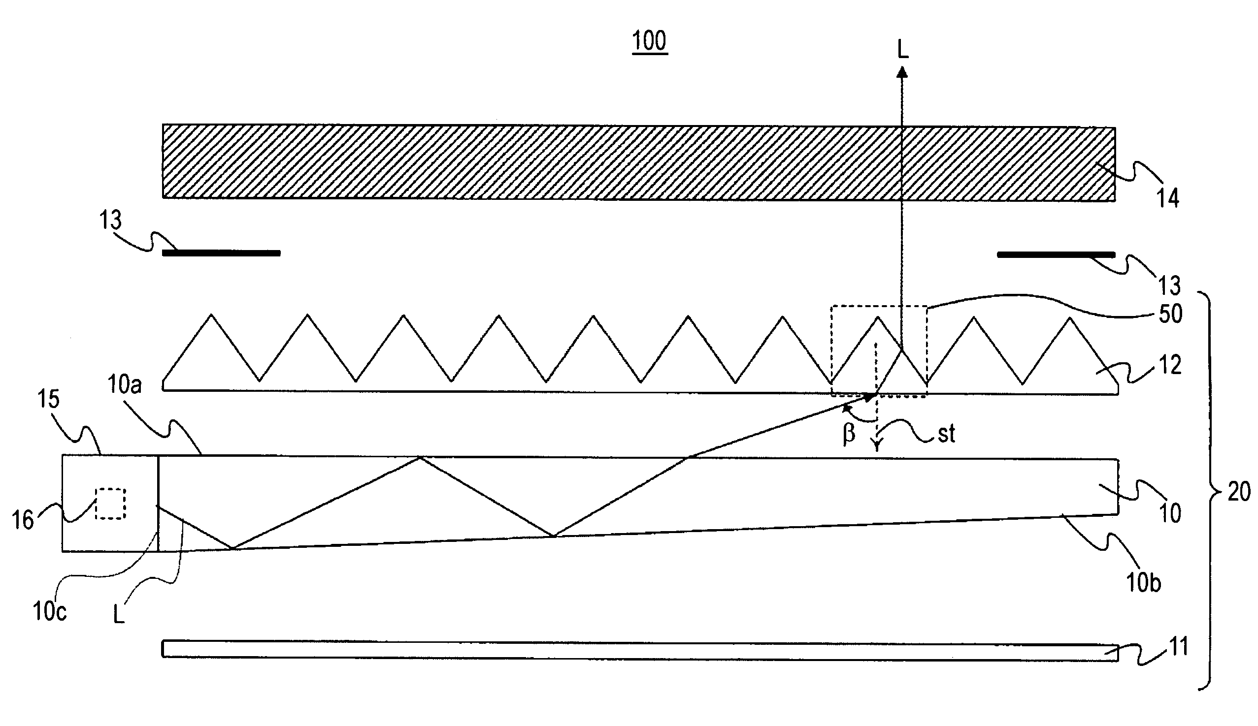
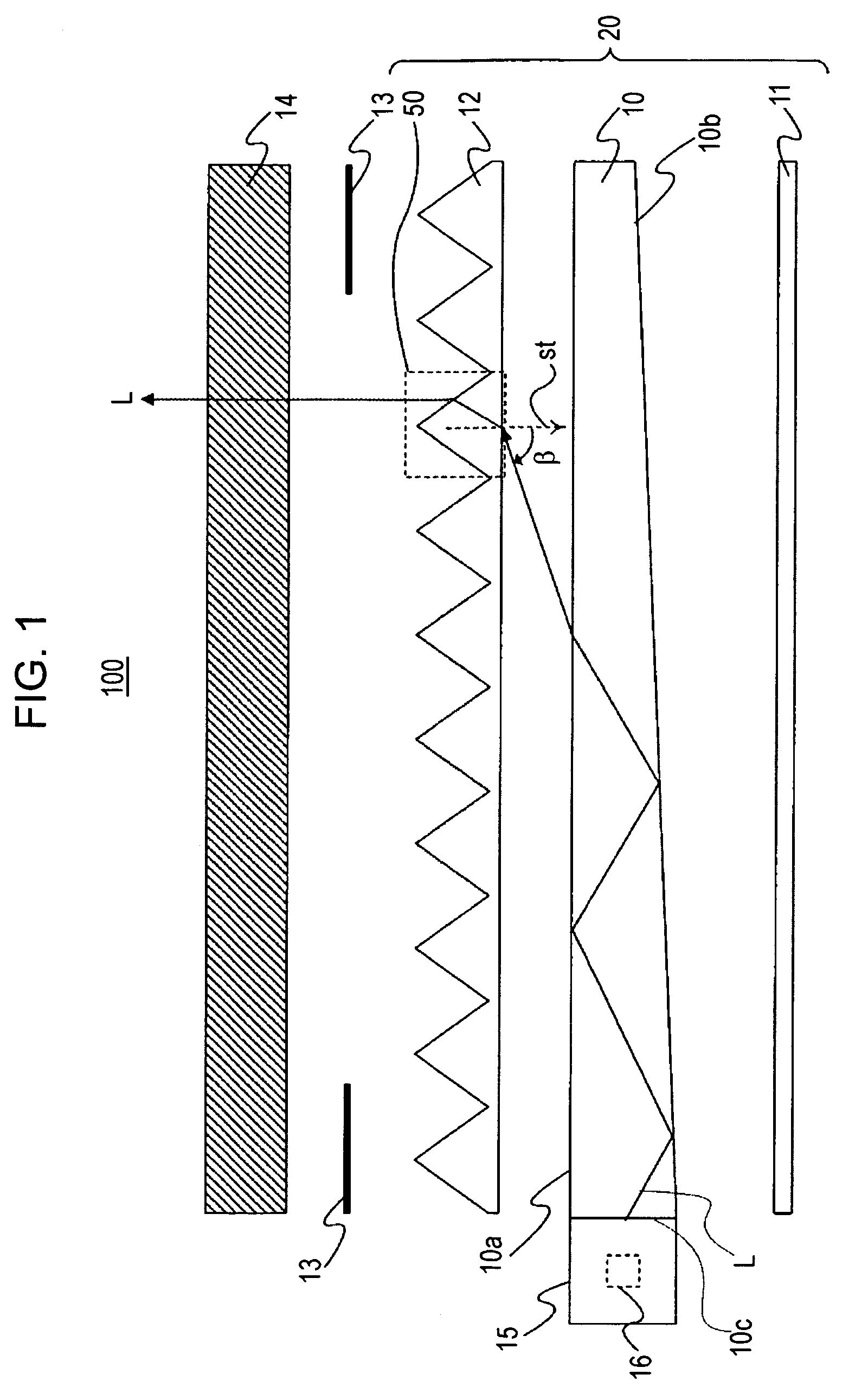
[0033]FIG. 1 shows the schematic structure of a liquid crystal display device 100 provided with an illuminating device according to the invention. In FIG. 1, an illuminating device 20 of the invention is a surface-emitting-type illuminating device used as a backlight unit, for example, in the liquid crystal display device 100. The illuminating device 20 includes an optical waveguide 10 having a light source 15 at one end, a reflective sheet 11 provided below the optical waveguide 10, and a prism sheet 12 provided above the optical waveguide 10. The illuminating device 20 is adhered to a liquid crystal panel 14 by a double-sided tape 13.

[0034]In the illuminating device 20, a light source 15 includes a plurality of LEDs 16 serving as point light sources and emits light to an end surface (hereinafter, referred to as a ‘light i...


PUM


Abstract

An illuminating device includes a light source, an optical waveguide that emits light from the light source through an emission surface thereof, and a prism sheet that is provided on the emission surface side of the optical waveguide. In the illuminating device, the following relationship is established between a refractive index x of the prism sheet and an apex angle y of a prism: y=107.86x−140.43+M (−4≦M≦4).

Description

BACKGROUND[0001]1. Technical Field[0002]The present invention relates to an illuminating device, such as a backlight unit used for, for example, a liquid crystal display device of a cellular phone.[0003]2. Related Art[0004]A liquid crystal display device includes a backlight unit on the rear surface side of a liquid crystal display panel to perform transmissive display. In general, the backlight unit is composed of an illuminating device including a light source, an optical waveguide for emitting light from the light source to the rear surface of the liquid crystal display panel as surface light, a sheet for diffusing light emitted from the optical waveguide, and a prism sheet for condensing light. Light incident on the optical waveguide from the light source travels in the optical waveguide while repeatedly reflecting from an emission surface and a reflective surface of the optical waveguide, and is then emitted from the emission surface to the outside.[0005]The light emitted from ...

Claims


Application Information

Patent Timeline
Patent Type & Authority Patents(United States)
IPC IPC(8): F21V7/04
CPCG02B6/0046G02B6/0053G02B6/0051G02B6/0048
Inventor ONISHI, YASUNORI
Owner BOE TECH GRP CO LTD
Why Eureka
Try Eureka