Exposed-spring female terminal

a terminal and spring technology, applied in the field of female terminals, can solve the problems of reduced rigidity of resilient contact pieces, difficult to secure an adequate contact pressure, and difficult to do, so as to prevent the effect of preventing excessive deformation of leaf springs

Active Publication Date: 2008-09-02
JST MFG CO LTD
View PDF3 Cites 19 Cited by
  • Summary
  • Abstract
  • Description
  • Claims
  • Application Information

AI Technical Summary

Benefits of technology

[0006]The present invention covers a female terminal in which a leaf spring is stored inside a tubular body, like the above-mentioned terminal fitting. One object of the present invention is to provide a female terminal wherein the width of a portion of a leaf spring to which a large bending force is loaded is widened than the rest thereof to increase a resilient force that can be obtained from the leaf spring, and in turn to make the female terminal more compact or enhance the contact pressure.
[0008]When a counterpart male terminal is inserted into this exposed-spring female terminal, the resilient deformation part of the leaf spring will be pushed by the male terminal to undergo resilient deformation in the height direction to provide a contact pressure between both the terminals. In this case, the largest bending force is loaded on a portion extending from the restrained part to the resilient deformation part of the leaf spring. However, as this portion has a plate width larger than the dimension between the inner faces of the two vertical walls, thus providing the wider-width part, its flexural rigidity is higher in comparison with a conventional case wherein the width of the leaf spring is narrower than the width of the internal space of the body. Accordingly, even when one attempts to make the female terminal more compact by reducing the body width less than that of a conventional female terminal, a sufficient contact pressure will be secured. Moreover, it is also possible to enhance the contact pressure of the leaf spring without changing the width of the body in comparison with a conventional female terminal. Furthermore, as the body is made tubular, a high rigidity is provided, and the body will be hardly deformed under external forces. As the leaf spring is retained inside the body except its wider-width part, the leaf spring is protected against external forces.
[0014]With this arrangement, when a counterpart male terminal is inserted into this exposed-spring female terminal, the resilient deformation part of the leaf spring will be pushed by the male terminal to undergo resilient deformation in the height direction, approaching toward the restrained part, and a contact pressure will be obtained between both the terminals. In this case, the largest bending force is loaded on the end on the curved part side of the restrained part and the curved part of the resilient deformation part. However, as this portion is the wider-width part, its flexural rigidity is larger than the conventional case wherein the width of the leaf spring is made narrower than the width of the internal space of the body. Accordingly, if one attempts to make the female terminal smaller by reducing the width of the body than that of a conventional female terminal, a sufficient contact pressure will be secured. Moreover, it is also possible to enhance the contact pressure of the leaf spring without changing the body width in comparison with a conventional female terminal. Furthermore, as the body is made tubular, a high rigidity is secured, and the body will be hardly deformed under external forces. As the leaf spring is retained inside the body except the wider-width part, the leaf spring is protected against external forces.
[0019]The exposed-spring female terminal of the present invention may be provided with a stopper on the vertical wall between the leaf spring and the lateral wall, said stopper is to prevent excessive deformation of the leaf spring by contacting the leaf spring almost undergoing excessive deformation.
[0020]With this arrangement, the leaf spring is prevented from undergoing excessive deformation.

Problems solved by technology

Accordingly, if one attempts to make the terminal fitting more compact by reducing the width of the terminal body, the width of the resilient contact piece will be narrowed and the flexural rigidity of the resilient contact piece will be reduced, making it difficult to secure an adequate contact pressure.
Moreover, if one attempts to enhance the contact pressure of the resilient contact piece without altering the width of the terminal body, it will be difficult to do so.

Method used


Image

  • Exposed-spring female terminal
  • Exposed-spring female terminal
  • Exposed-spring female terminal

Examples


Embodiment Construction

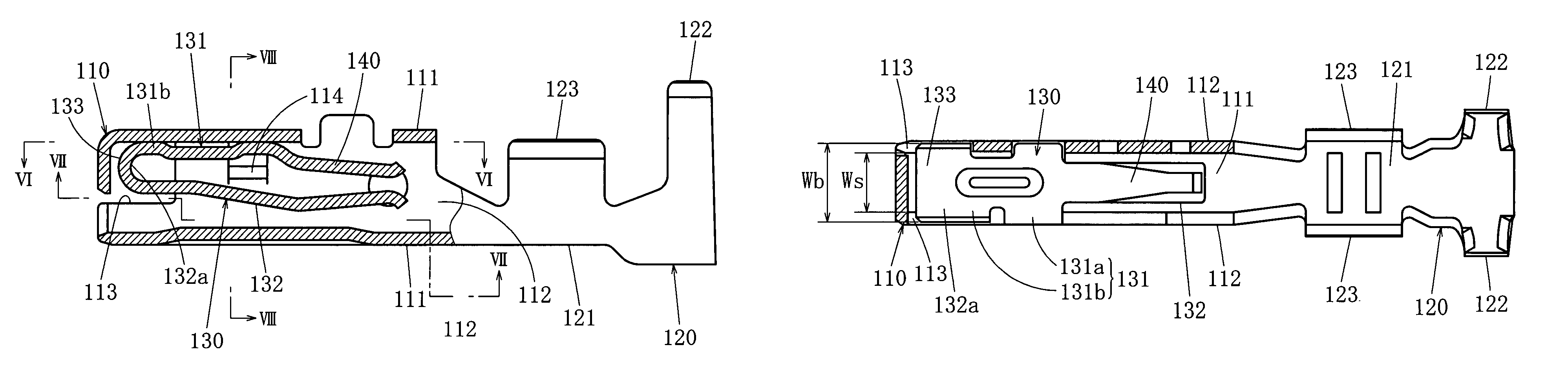
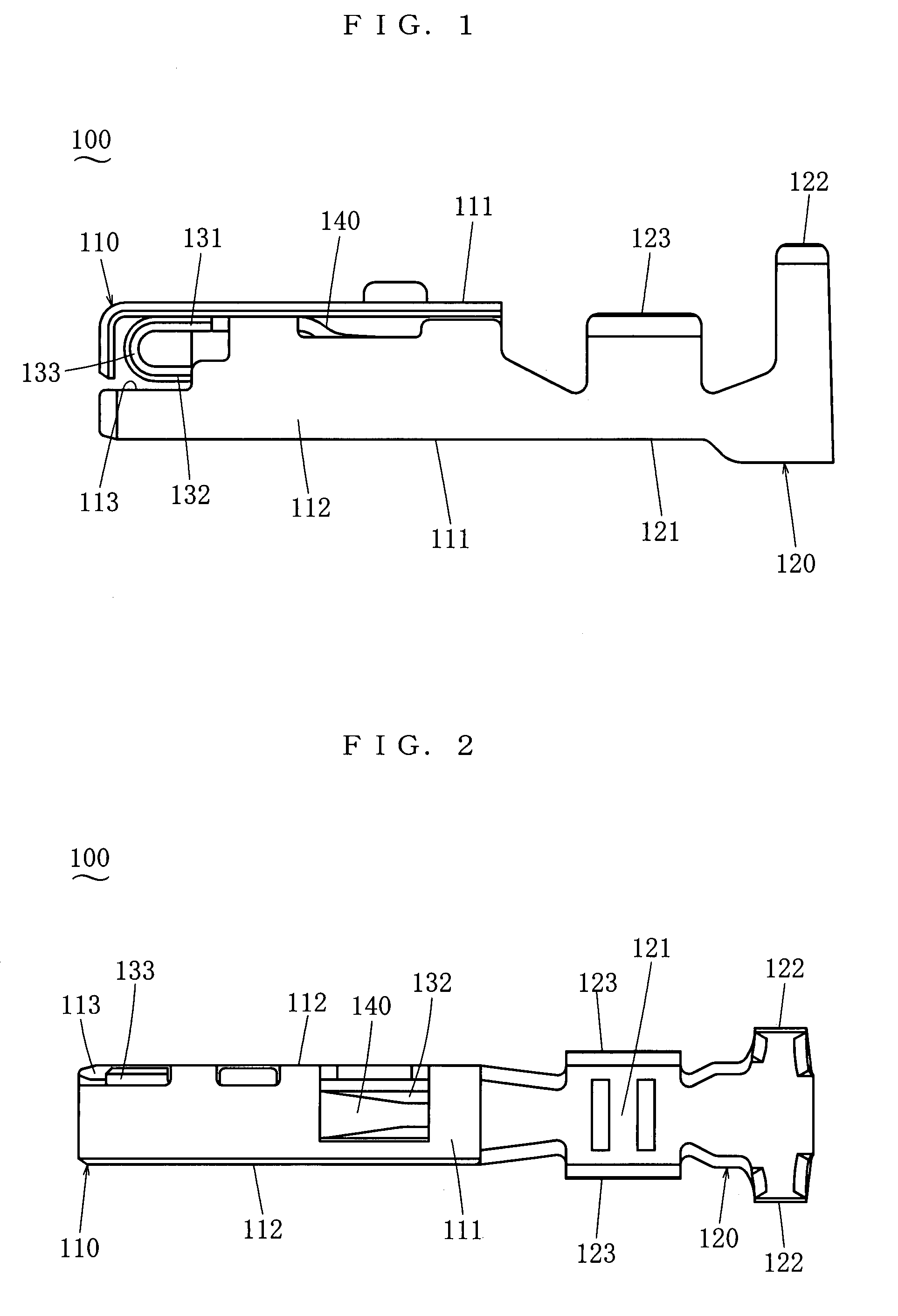
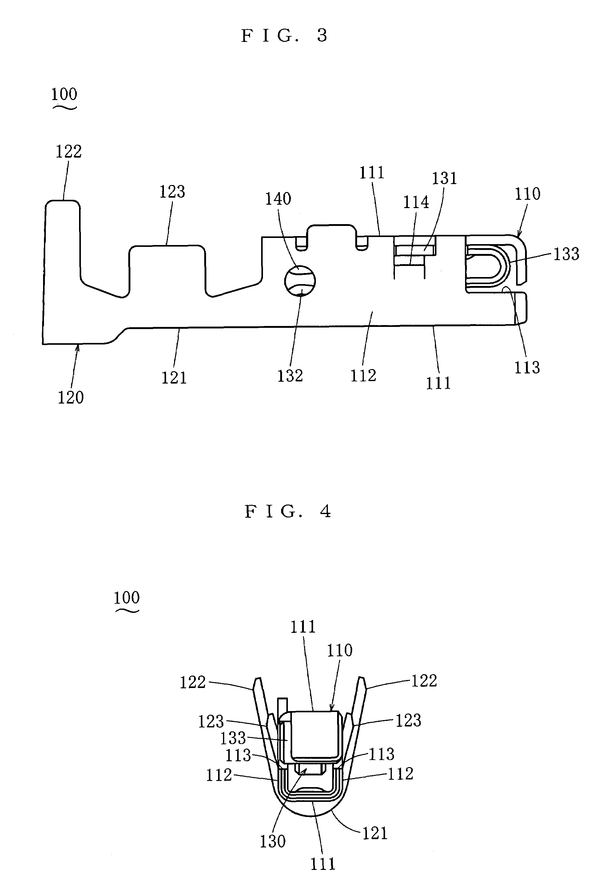
[0037]In the following, some embodiments of the present invention will be described. FIG. 1 through FIG. 8 illustrate the exposed-spring female terminal 100 of the first embodiment. This exposed-spring female terminal 100 fits with a well-known male terminal such as plug (not illustrated). It is suffice for the male terminal to have a rod-shaped or plate-shaped contact part having electric conductivity. The exposed-spring female terminal 100 may be used by storing it inside a housing (not illustrated) or it may be used as it is. In the following, a height direction, a width direction and a depth direction all perpendicular to each other are defined, and the description will be given on the basis of them. With reference to FIG. 1, the left-right direction in the diagram is the depth direction, the left is the front and the right is the rear, the top-bottom direction of the diagram is the height direction, and the direction perpendicular to the paper plane of the diagram is the width ...


PUM


Abstract

The present invention is an exposed-spring female terminal comprising a tubular body having two lateral walls and two vertical walls and extending in a depth direction; a connecting part being arranged with the body on a rear side in the depth direction, being provided integrally with the body and being structured to connect to an electric wire, etc.; and a leaf spring being arranged inside the body, with the plate width direction being substantially aligned with the width direction, and having a restrained part restrained by the body and a resilient deformation part extending from the restrained part in the depth direction when seen in the height direction and being capable of resilient deformation in the height direction; and the leaf spring being provided with a wider-width part extending from the restrained part to the resilient deformation part, of which plate width being larger than the dimension between the inner faces of the two vertical walls; and the two vertical walls being provided with openings for receiving the wider-width part.

Description

BACKGROUND OF THE INVENTION[0001]1. Field of the Invention[0002]The present invention belongs to a technical field of female terminals comprising a tubular body, a connecting part provided on said body to connect to an electric wire, and a leaf spring provided inside said body.[0003]2. Description of Related Art[0004]Japanese Patent Publication (Unexamined) No. HEISEI 10-55835 discloses a female terminal fitting comprising a terminal body and a protective cover covering a portion of said terminal body. The terminal body is structured by joining, via a joining part, an insertion part made by bending a thin metal plate and a barrel part to which an end of an electric wire is to be connected by crimping. Inside the insertion part, a resilient contact piece cut and raised from a bottom plate on a rear end side is provided. When a counterpart terminal is inserted into the female terminal fitting, the resilient contact piece will undergo elastic deformation to provide a contact pressure.S...

Claims


Application Information

Patent Timeline
Patent Type & Authority Patents(United States)
IPC IPC(8): H01R11/22
CPCH01R13/113
Inventor KANEKO, JUN
Owner JST MFG CO LTD
Why Eureka
Try Eureka