Vapor sensing instrument for ultra trace chemical detection

a technology of vapor sensing and chemical detection, which is applied in the direction of instruments, fluorescence/phosphorescence, chemical methods analysis, etc., can solve the problems of reducing the overall efficiency of the detection process, time-consuming, dangerous, and expensive task of landmine detection,

Inactive Publication Date: 2008-09-02
FLIR DETECTION
View PDF20 Cites 133 Cited by
  • Summary
  • Abstract
  • Description
  • Claims
  • Application Information

AI Technical Summary

Problems solved by technology

Landmine detection is a tedious, time consuming, dangerous, and expensive task.
However, these detection methods are indirectly sensing the target analyte, and each step in a secondary detection scheme lowers the overall efficiency of the detection process.

Method used


Image

  • Vapor sensing instrument for ultra trace chemical detection
  • Vapor sensing instrument for ultra trace chemical detection
  • Vapor sensing instrument for ultra trace chemical detection

Examples


Embodiment Construction

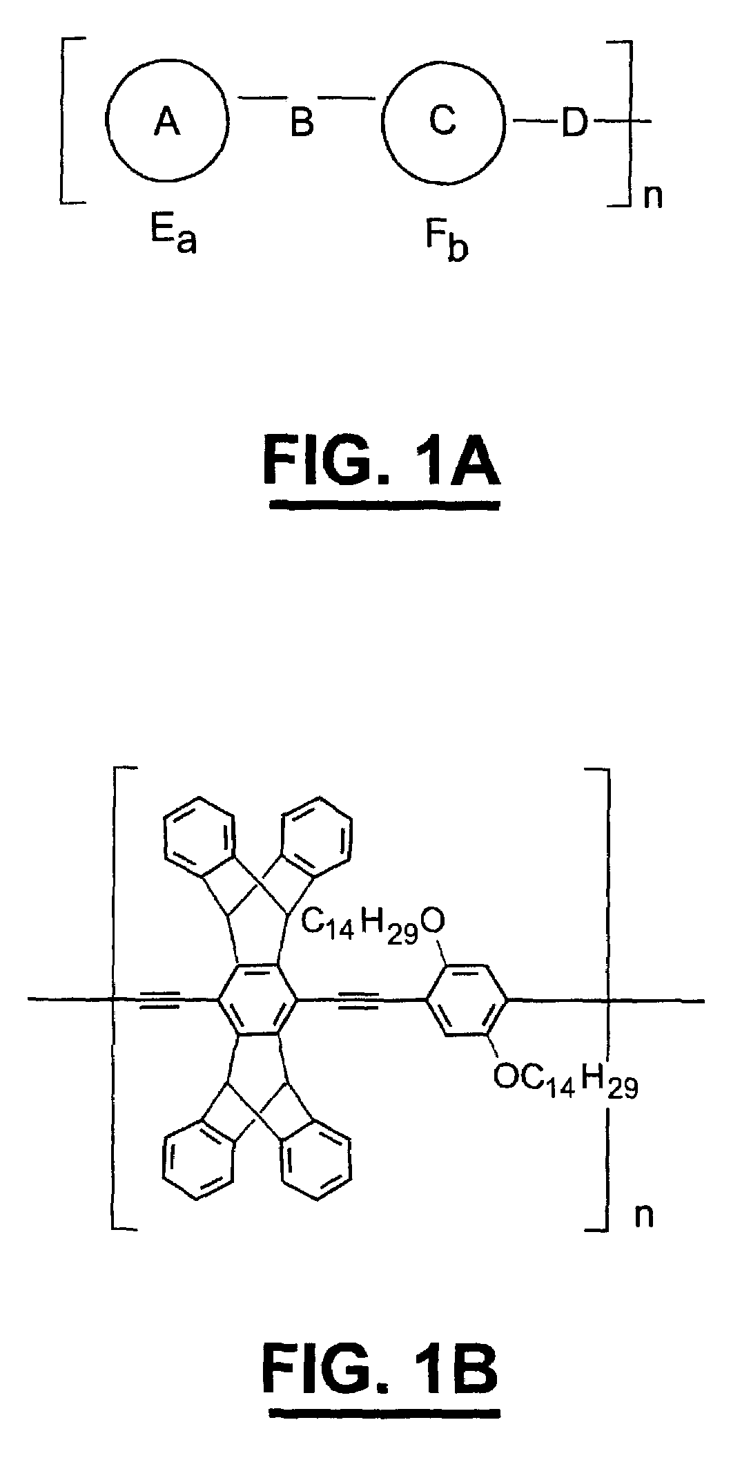
[0013]Certain molecules absorb photons of light of a certain wavelength and then emit a photon of light of a longer wavelength. This emission of light is known as fluorescence. Traditional fluorescence detection schemes measure a change in fluorescence intensity when a molecule of analyte interacts with a single fluorescent probe molecule. A photon of light must be absorbed by the fluorescent probe molecule while a molecule of analyte is interacting with the probe molecule. When the analyte molecule interacts with the fluorescent probe molecule, either an increase or decrease in the intensity of fluorescence is observed. “Emissive Polymers and Devices Incorporating These Polymers”, U.S. Ser. No. 60 / 084,247, filed on May 5, 1998, the entire content of which is hereby expressly incorporated herein by reference, describes a method for sensing an analyte through the luminescent and conductive properties of a class of polymer compositions which are referred to herein as amplifying fluore...


PUM

PropertyMeasurementUnit
widthaaaaaaaaaa
diameteraaaaaaaaaa
thicknessaaaaaaaaaa

Abstract

A detector for detecting vapors emitted from analytes includes a housing, a pump and a sensing assembly. The housing has an inlet, an outlet and an enclosed sensing volume therebetween. The pump communicates with the housing for moving a carrier sequentially through the enclosed sensing volume at a predetermined flow rate. The sensing assembly senses the vapors of the analyte delivered by the carrier as the carrier passes through the housing. The sensing assembly includes a sensing unit constructed of an amplifying fluorescent polymer, a source of excitation, a detector, and a convertor assembly.

Description

CROSS REFERENCE TO RELATED APPLICATIONS[0001]The present patent application is a continuation of U.S. Ser. No. 09 / 978,491, filed Oct. 16, 2001 now U.S. Pat. No. 6,558,626, entitled “VAPOR SENSING INSTRUMENT FOR ULTRATRACE CHEMICAL DETECTION”, which claims priority to the provisional patent application identified by U.S. Ser. No. 60 / 241,068 filed on Oct. 17, 2000. The entire content of each of these applications is hereby incorporated herein by reference.STATEMENT REGARDING FEDERALLY SPONSORED RESEARCH OR DEVELOPMENT[0002]Not Applicable.BACKGROUND OF THE INVENTION[0003]Landmine detection is a tedious, time consuming, dangerous, and expensive task. Perhaps a hundred million landmines are presently deployed on earth, notably in underdeveloped countries which scarcely have the resources to remove them. Hence, the development of technologies which can expedite landmine removal are in demand. For instance, the United States government has initiated a “Dog's Nose Research Program” through ...

Claims


Application Information

Patent Timeline
Patent Type & Authority Patents(United States)
IPC IPC(8): G01N21/64G01N21/05G01N21/66G01N21/77
CPCG01N21/05G01N21/643G01N2021/6432Y10T436/17G01N2021/7786Y10T436/11G01N2021/6439
Inventor AKER, CRAIG A.CUMMING, COLIN J.FISHER, MARK E.FOX, MICHAEL J.IAGRONE, MARCUS J.REUST, DENNIS K.ROCKLEY, MARK G.TOWERS, ERIC S.
Owner FLIR DETECTION
Why Eureka
Try Eureka